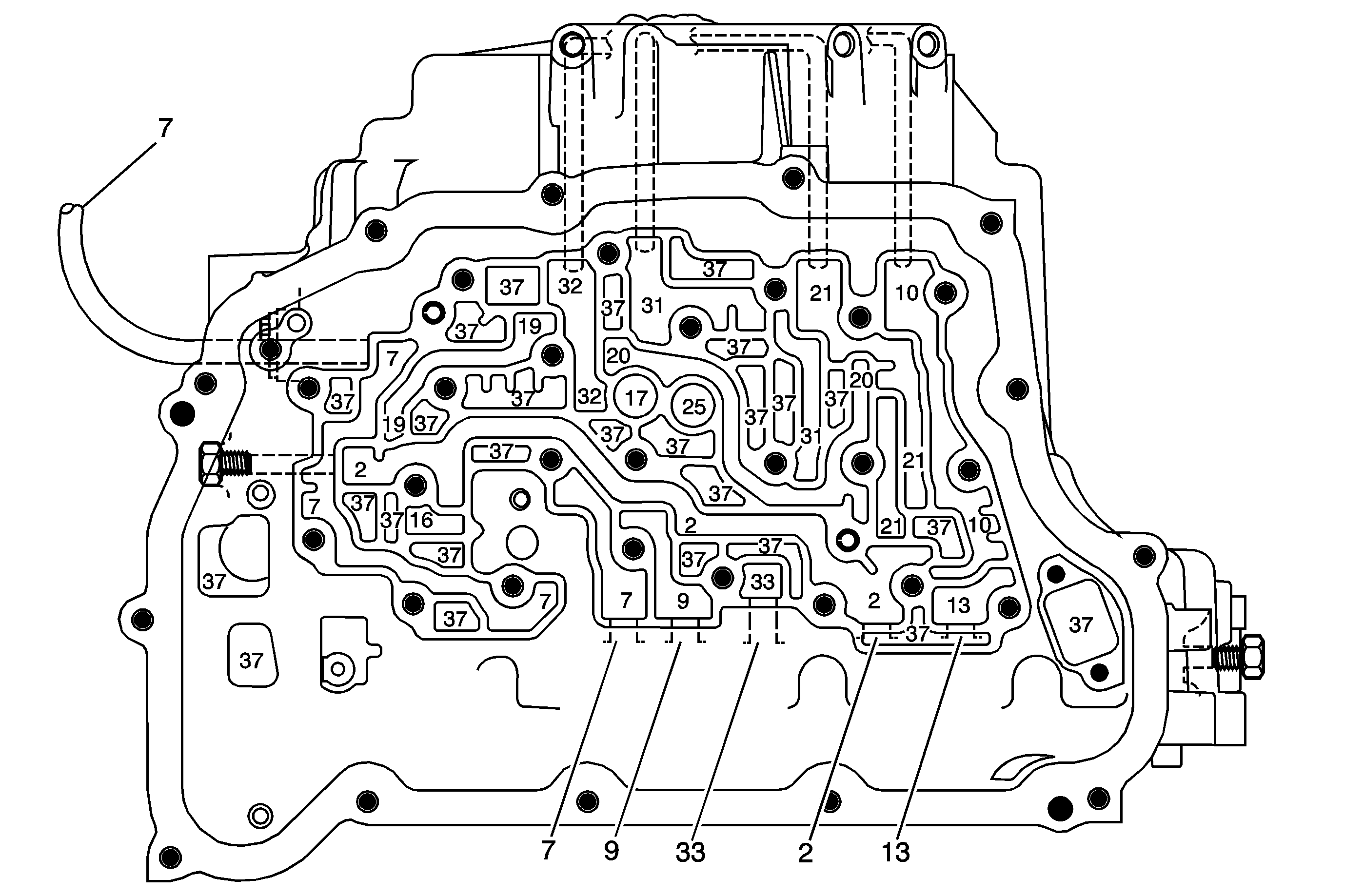
| Figure 1: |
Case - Control Valve Body Side (Left)
|
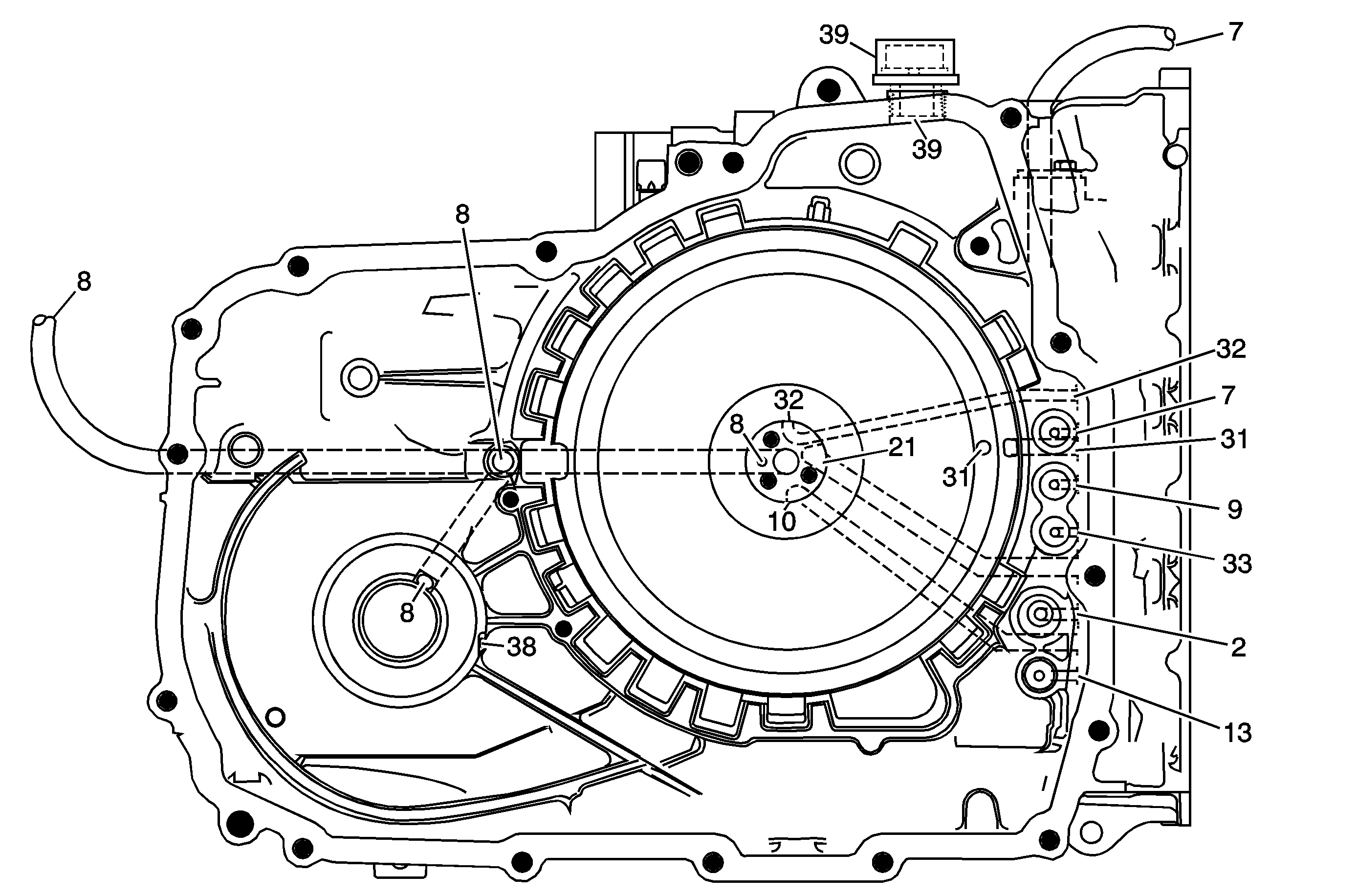
| Figure 2: |
Case - Pump Side (Back)
|
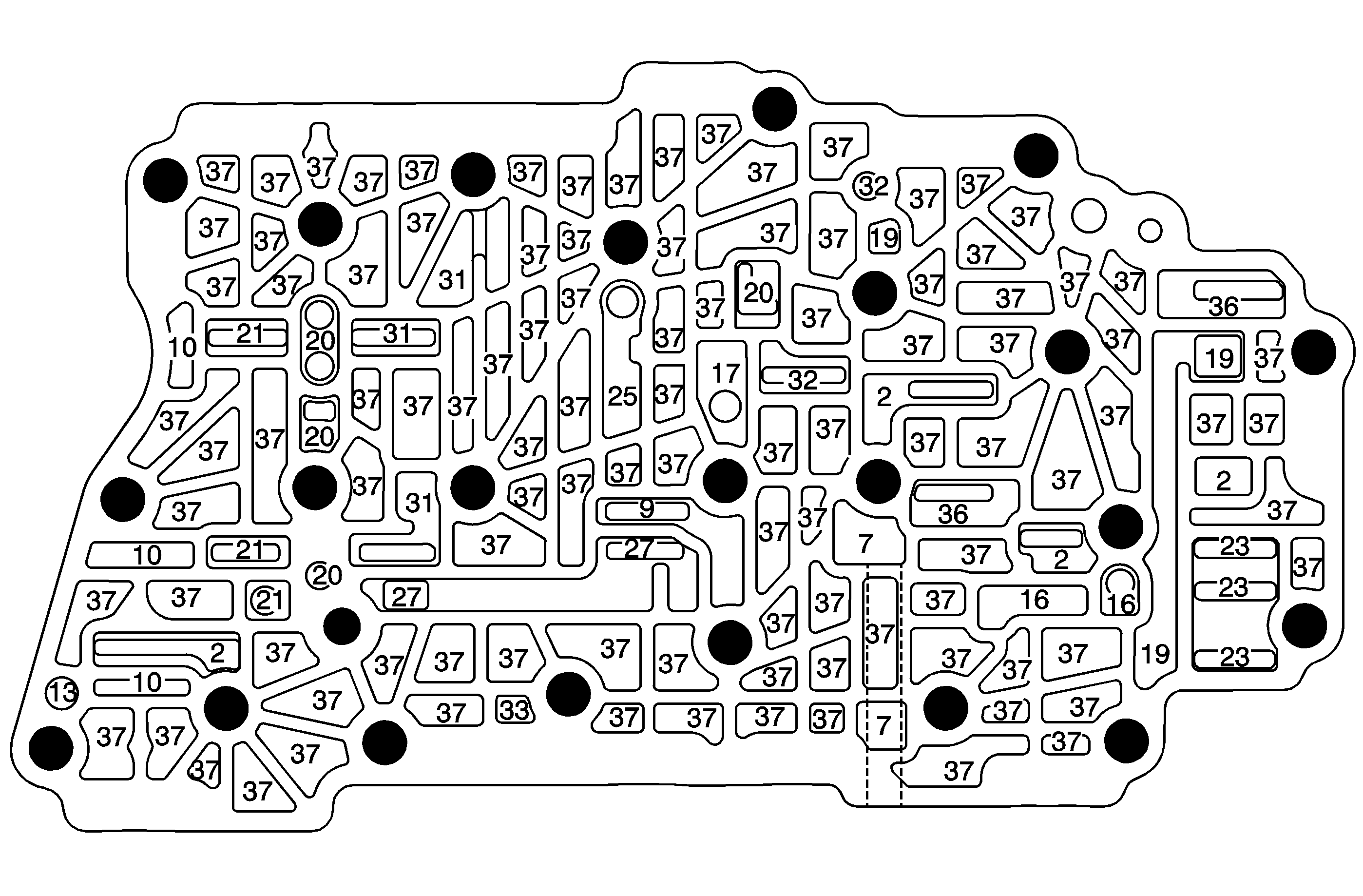
| Figure 3: |
Control Valve Body - Case Side (Left)
|
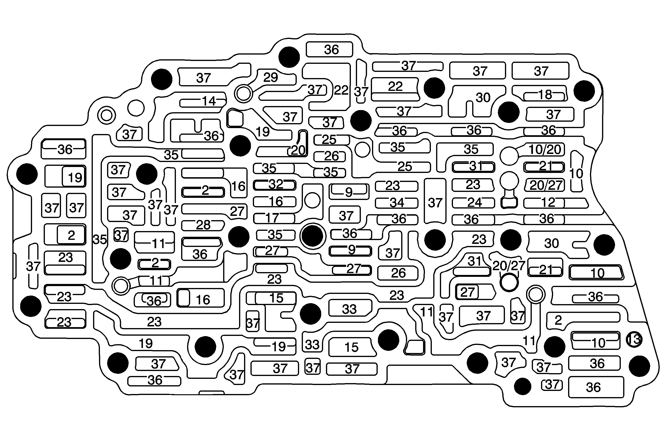
| Figure 4: |
Control Valve Body - Channel Plate Side (Right - No Valves)
|
| Figure 5: |
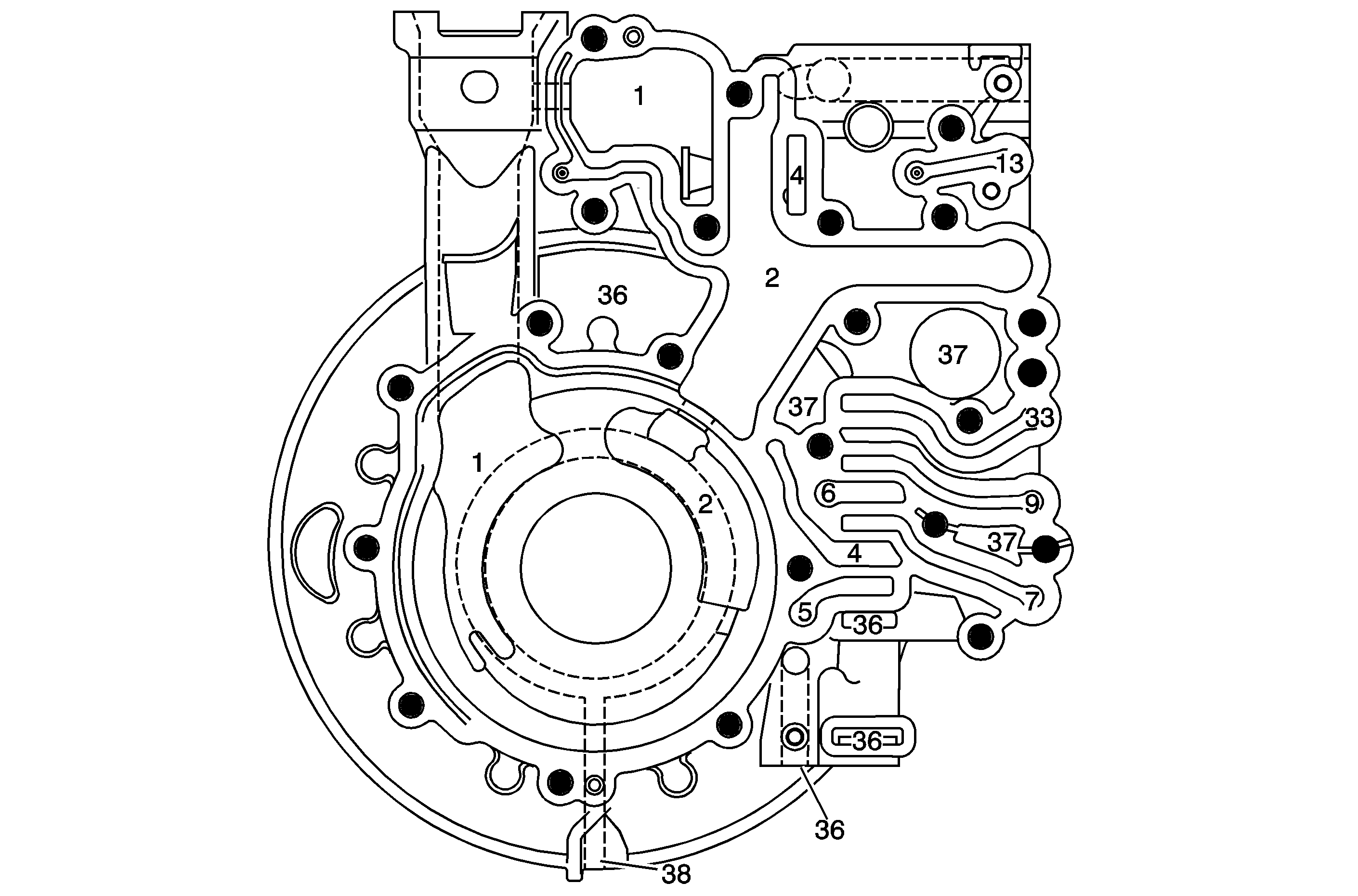
Pump Body - Pump Cover Side (Front)
|
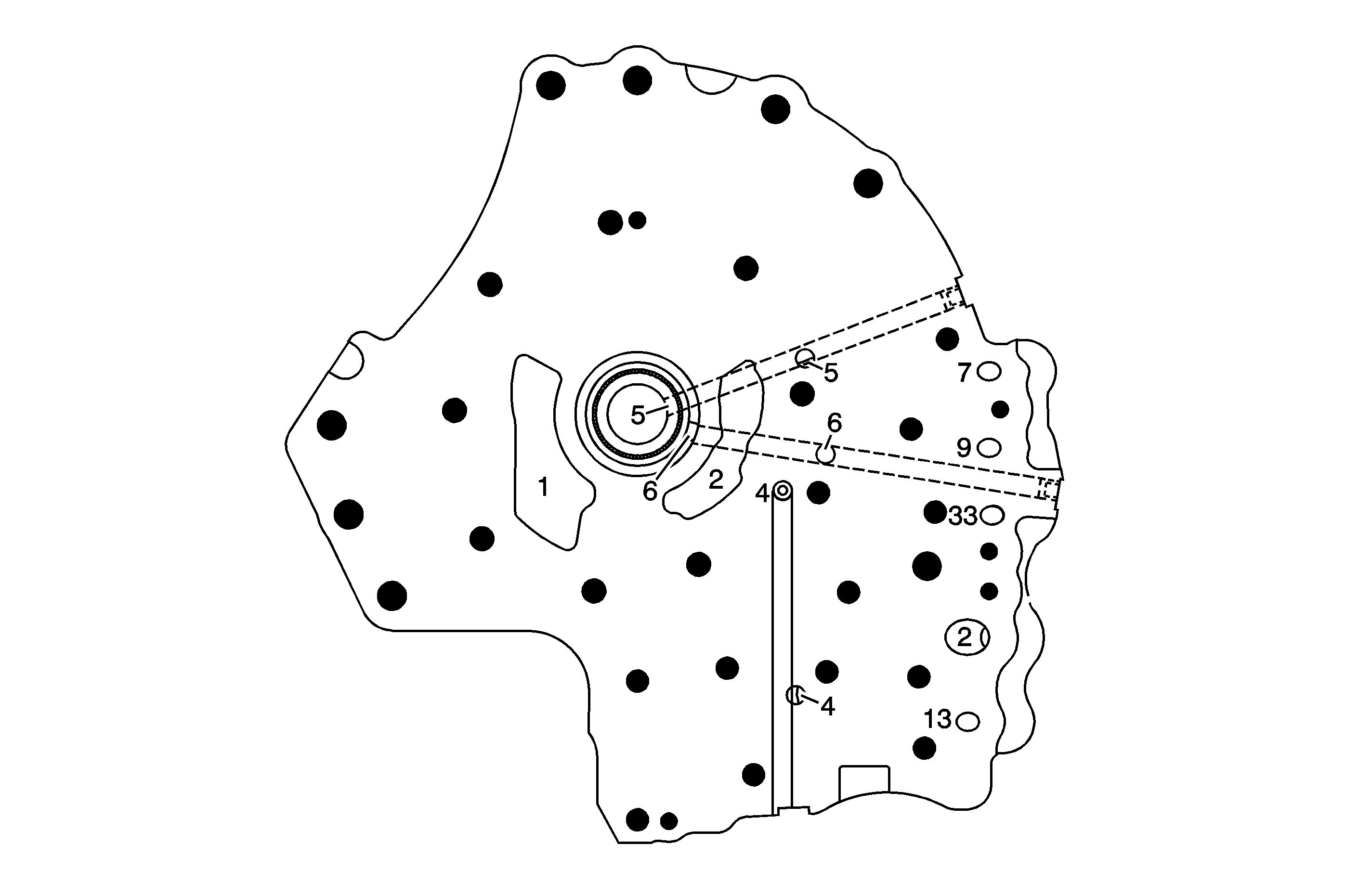
| Figure 6: |
Pump Cover - Pump Body Side (Back)
|
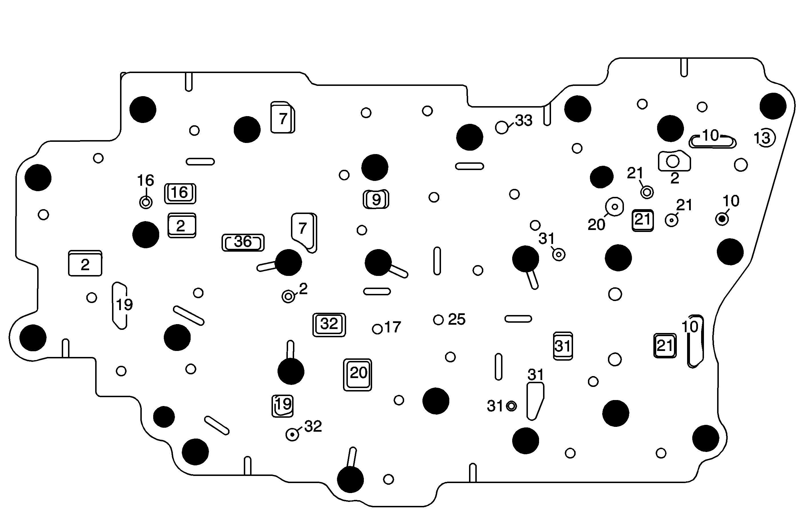
| Figure 7: |
Spacer Plate (12) - Case Side (Left)
|
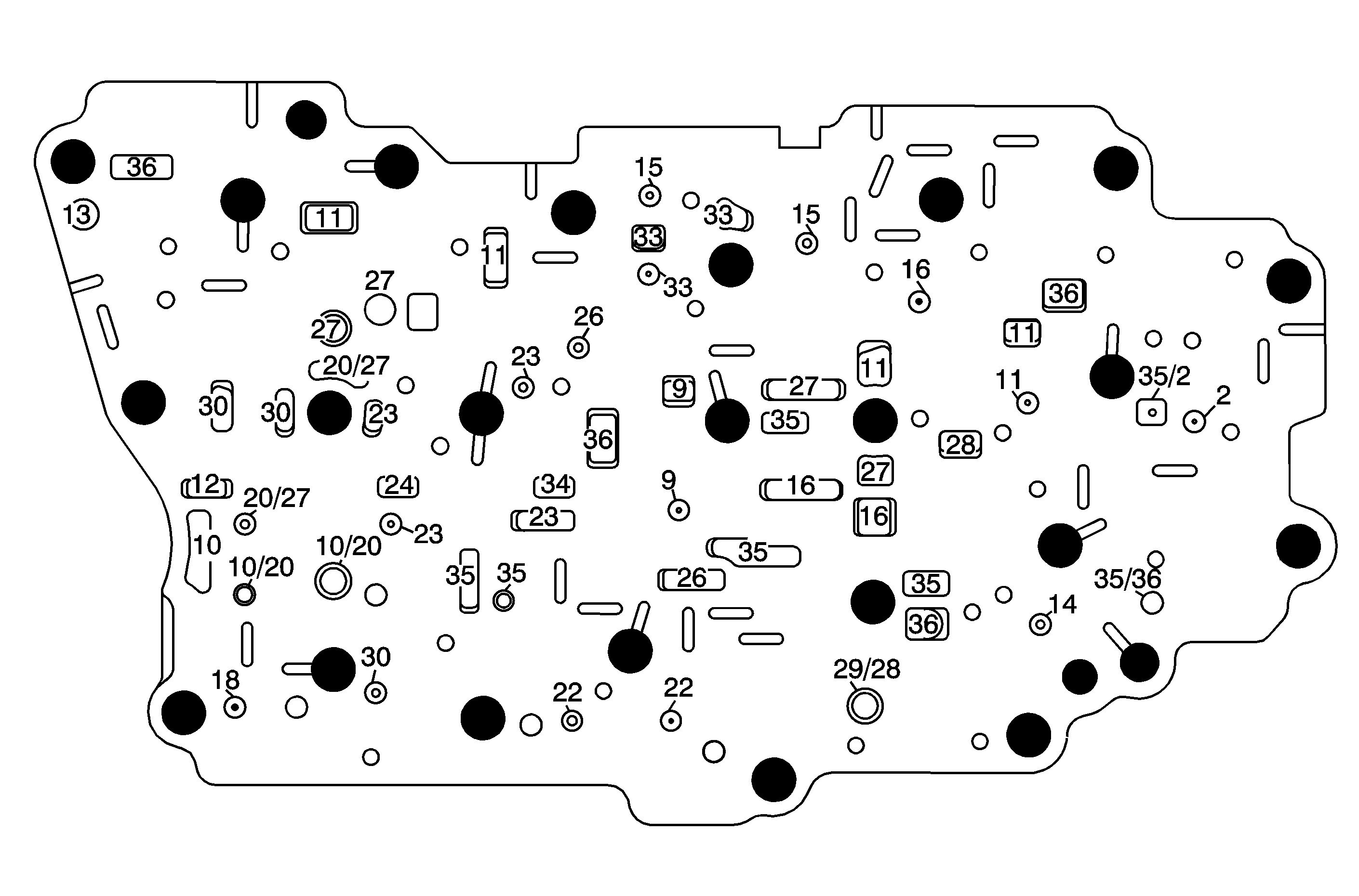
| Figure 8: |
Spacer Plate (402) - Channel Plate Side (Right)
|
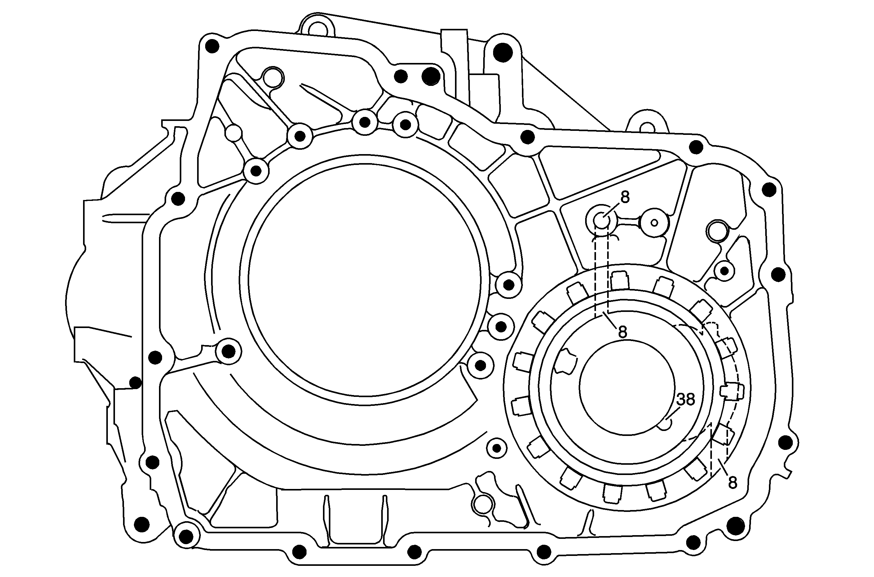
| Figure 9: |
Torque Converter Clutch Housing - Pump Side (Front)
|
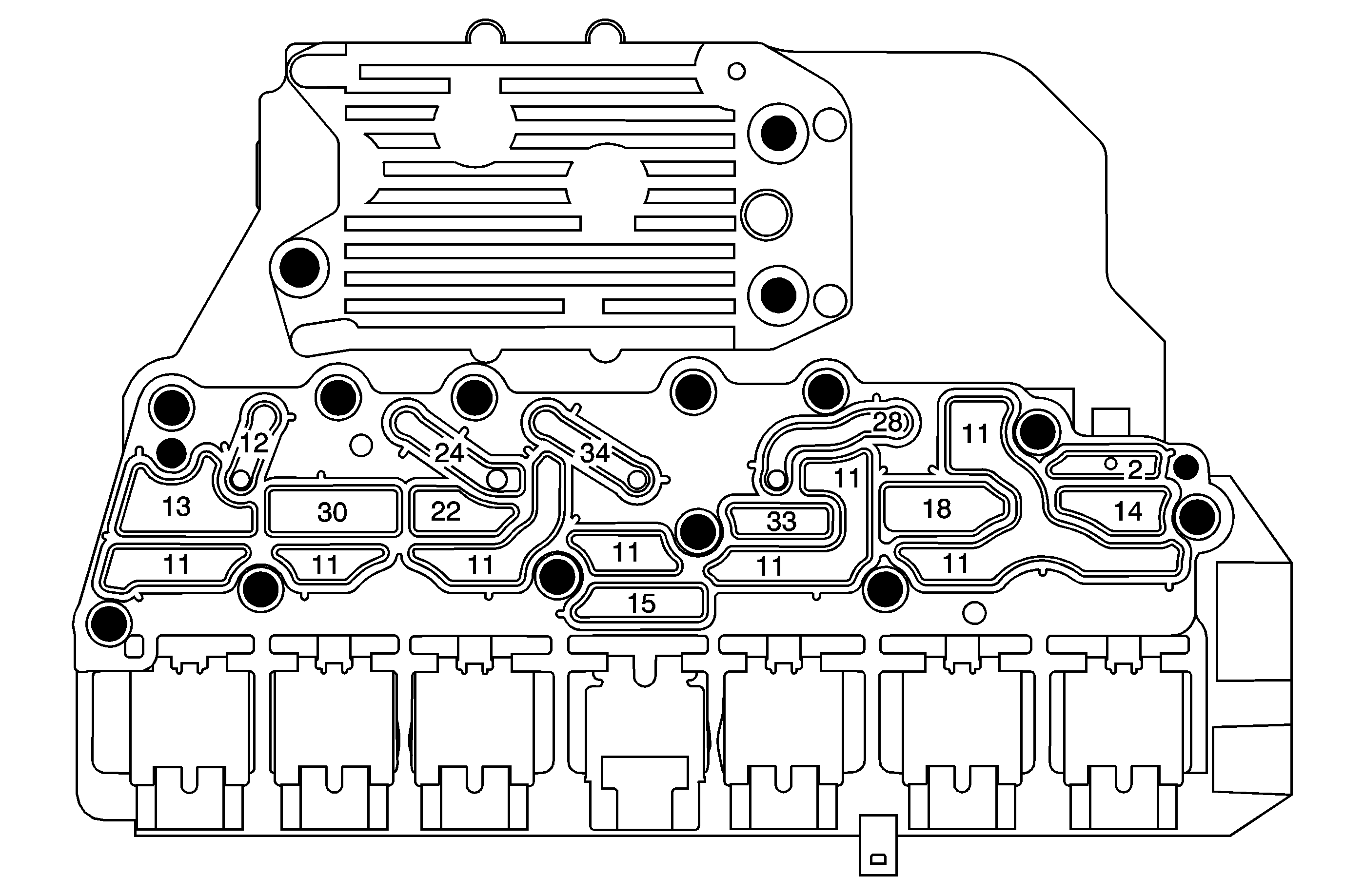
| Figure 10: |
Control Solenoid Valve Assembly with Filter Plate - Channel Plate Side (Front)
|
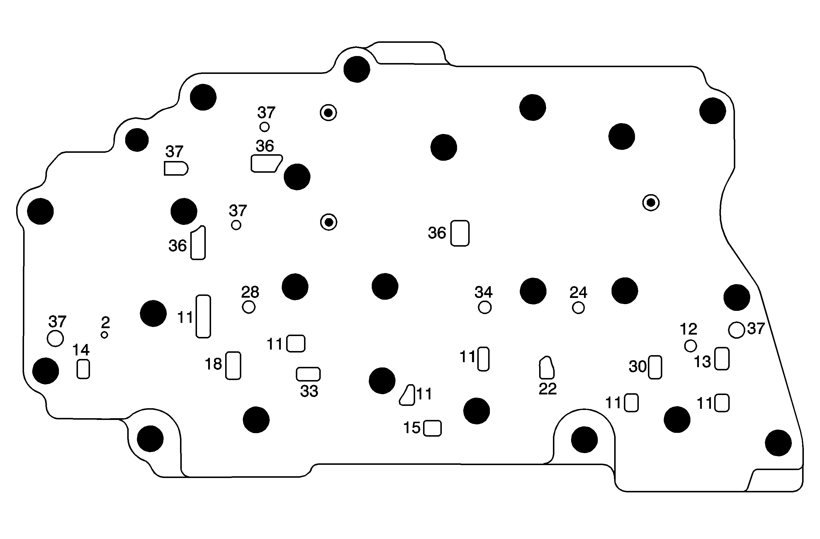
| Figure 11: |
Channel Plate - Control Solenoid Valve Assembly Side (Right)
|
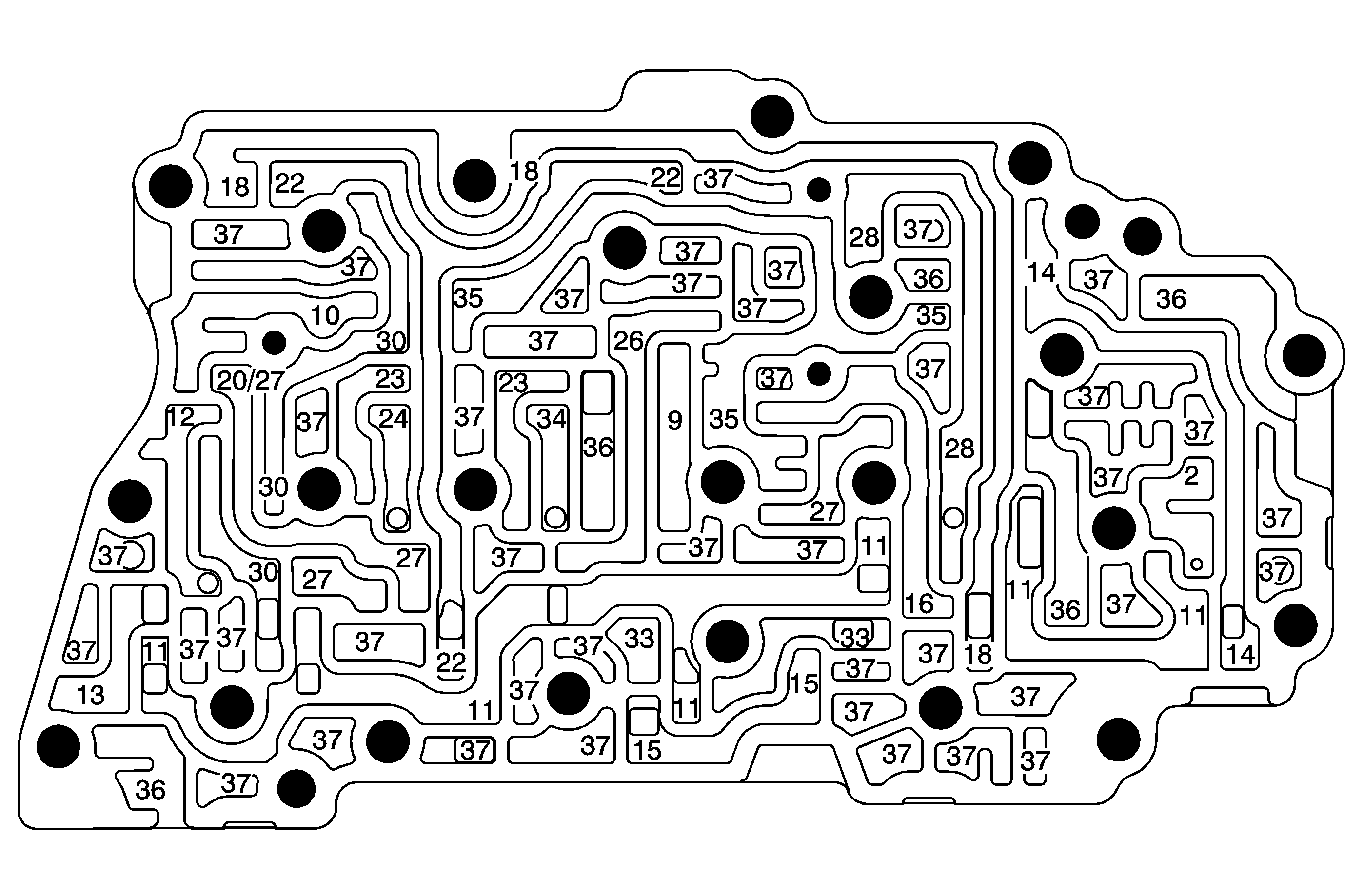
| Figure 12: |
Channel Plate - Control Valve Body Side (Left)
|