For 1990-2009 cars only
Special Tools
J 45059 Angle Meter
Removal Procedure
- Raise and support the vehicle. Refer to Lifting and Jacking the Vehicle.
- Remove the tires and wheels. Refer to Tire and Wheel Removal and Installation.
- Remove the rear muffler assembly from the vehicle. Refer to Exhaust Muffler Replacement.
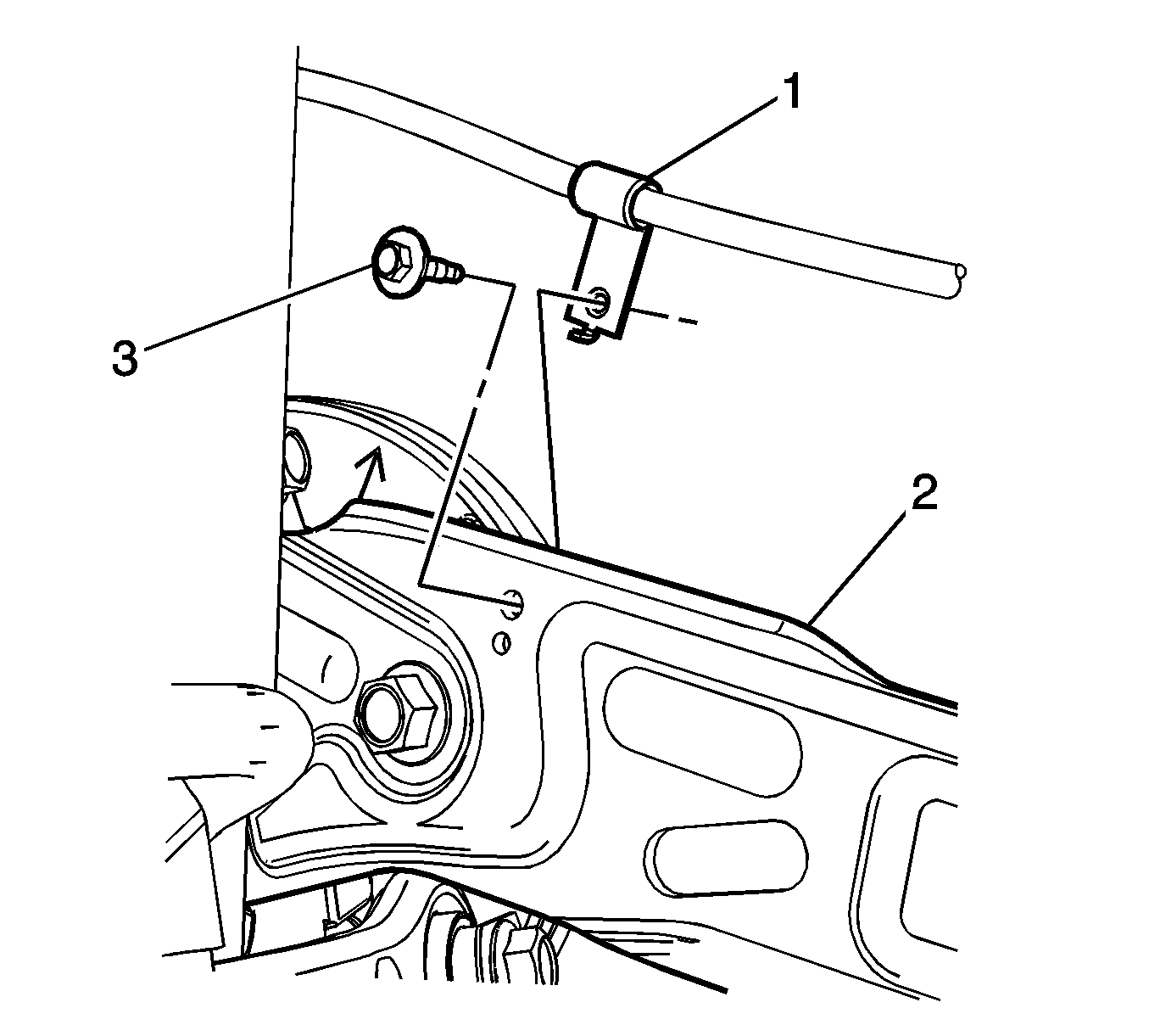
- Remove the park brake cable retaining bolt (3), park brake cable (1), from the trailing arm assemblies (2).
- Disconnect the wheel speed sensor electrical connector at the right rear trailing arm mounting bracket.
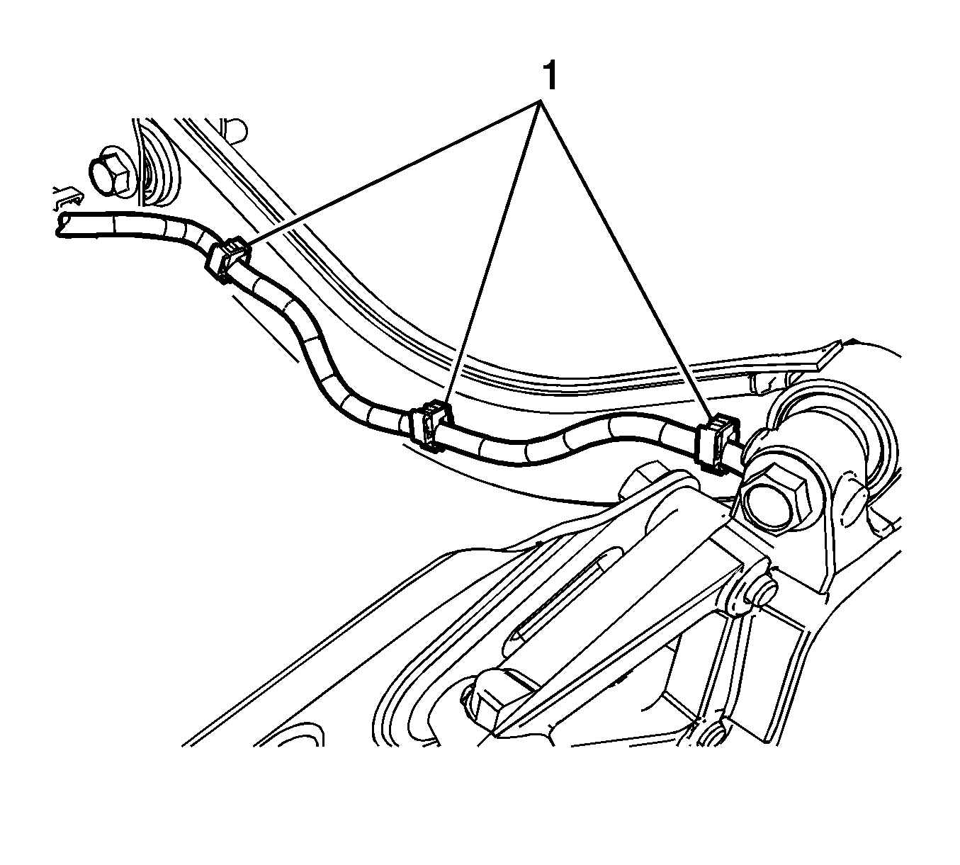
- Remove the wheel speed sensor wiring harness from the trailing arm bracket at the right rear of the vehicle.
- Remove the toe links from the from the vehicle. Refer to Toe Link Replacement.
- Remove the lower control arms from the vehicle. Refer to Rear Axle Lower Control Arm Replacement.
- Remove the rear knuckles from the vehicle. Refer to Knuckle Replacement.
- Secure the rear support to a transmission jack stand.
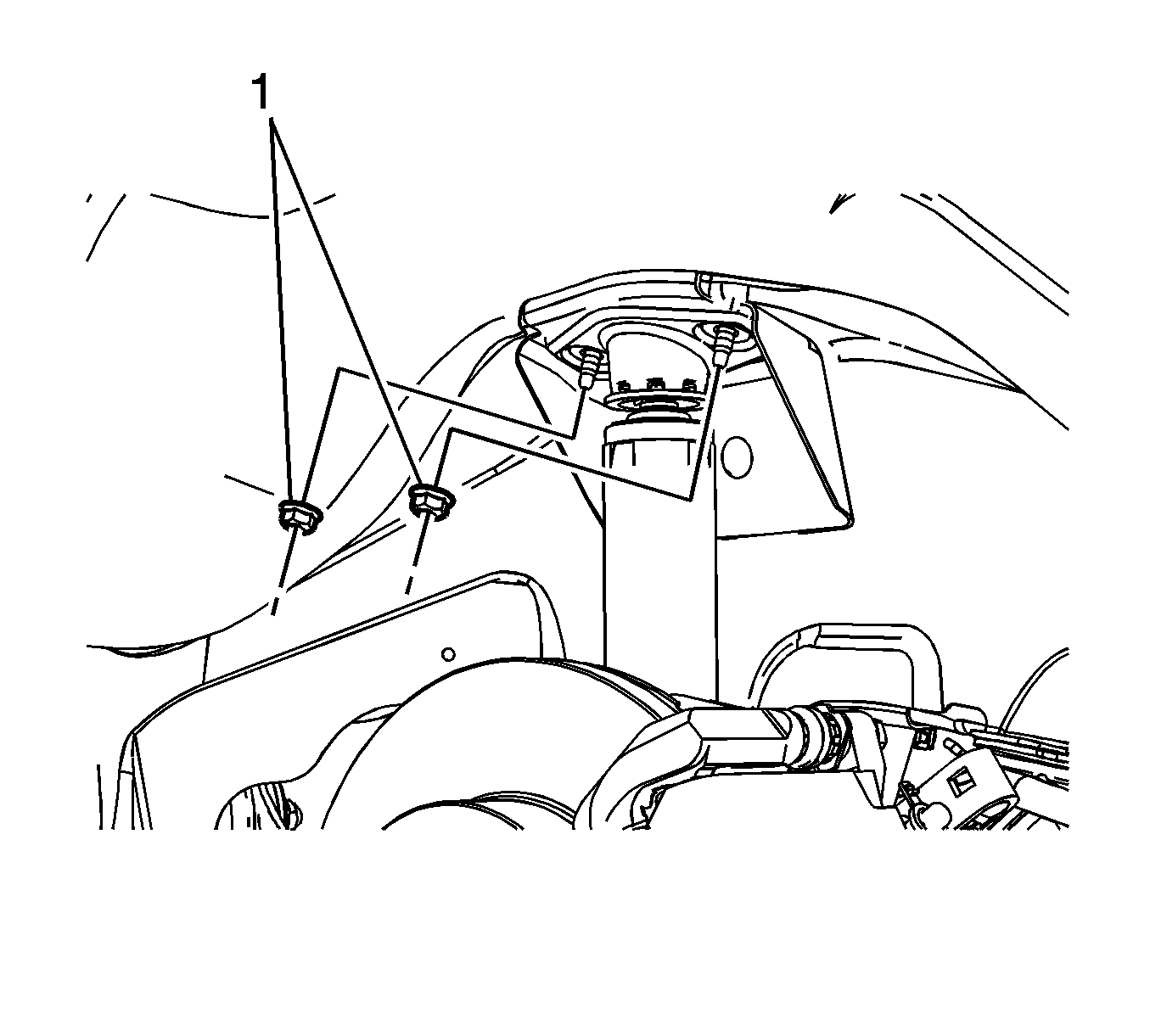
- Remove the upper shock absorber mounting bolts (1).
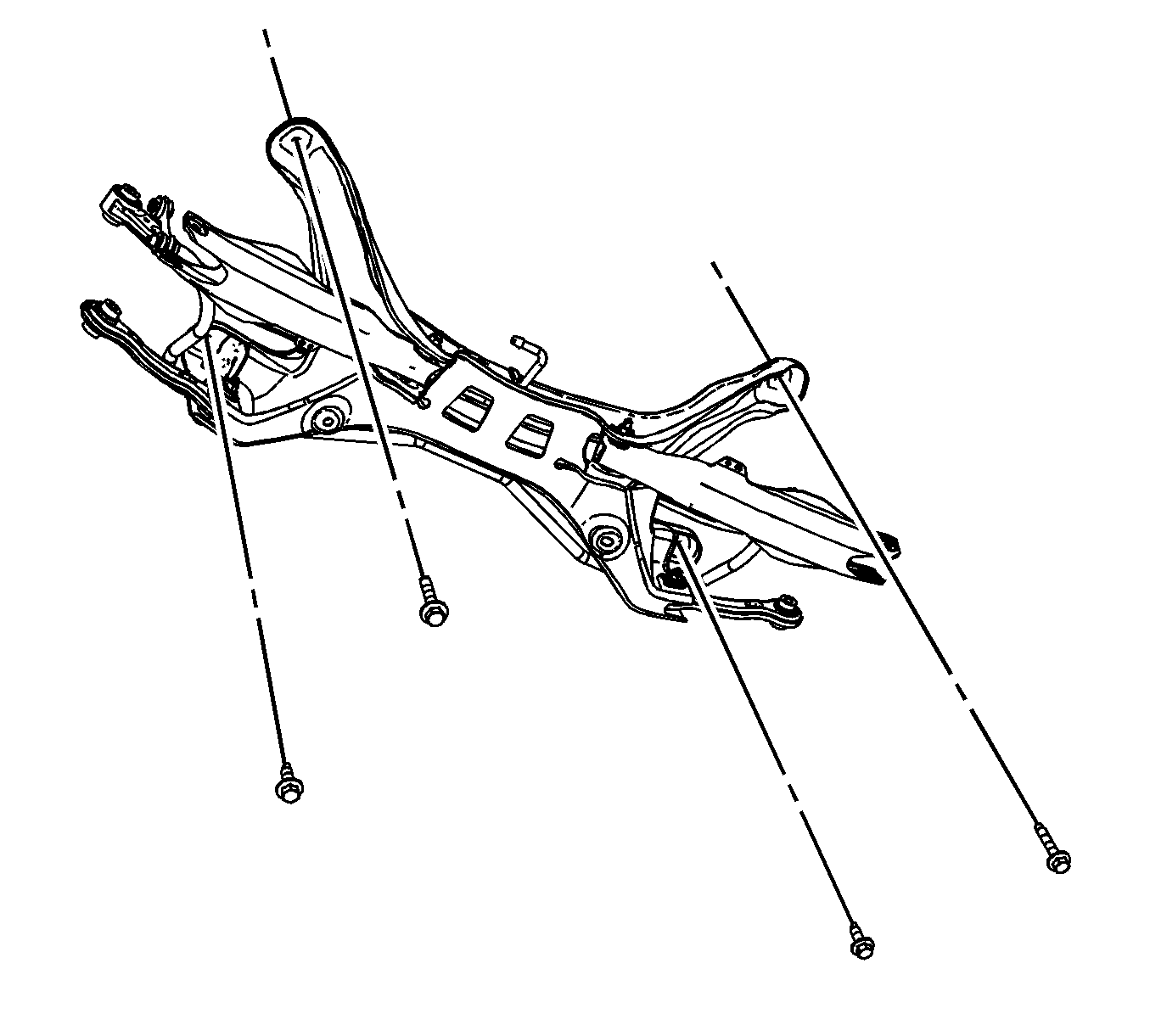
- Remove the mounting bolts for the support.
- With the aide of an assistant, lower the support.
- Remove the support from the transmission jack stand.
- Remove the wheel speed sensor wiring harness from the upper control arms and the support.
- Remove the upper control arm nuts and bolts from the support.
- Remove the upper control arms from the support.
- Remove the stabilizer shaft from the support.
Note: If lowering the support to service other rear suspension components, perform steps 4, 5, 7, 9, 10, 11, and 12.
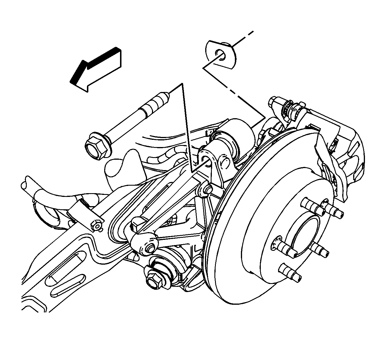
Installation Procedure
Note: When transferring any suspension components, refer to each suspension component replacement procedure for the proper torque specifications.
- Install the rear stabilizer shaft assembly on the support. Refer to Stabilizer Shaft Replacement.
- Install the upper control arm on the support.
- Install the upper control arm nuts and bolts to the support. Refer to Rear Axle Upper Control Arm Replacement.
- Install the wheel speed sensor wiring harness on the upper control arms and the support.
- Secure the rear support to a transmission jack stand.
- Raise the support into position with the aide of an assistant.
- Install the support mounting bolts and tighten to 100 N·m (74 lb ft).
- Remove the transmission jack from the support.
- Install the knuckle assembly to the support. Refer to Knuckle Replacement.
- Install the upper shock absorber nuts. Refer to Shock Absorber Replacement.
- Install the lower control arm assembly. Refer to Rear Axle Lower Control Arm Replacement.
- Install the toe links to the support. Refer to Toe Link Replacement.
- Install the park brake cable retaining bolt (3), park brake cable (1), on the trailing arm assemblies (2).
- Install the rear wheel speed sensor wiring harness to the right rear trailing arm mounting bracket.
- Reconnect the wheel speed sensor electrical connector at the right rear trailing arm.
- Install the rear muffler assembly. Refer to Exhaust Muffler Replacement.
- Install the tire and wheel assemblies. Refer to Tire and Wheel Removal and Installation.
- Lower the vehicle.
- Realign the rear suspension. Refer to Wheel Alignment Measurement.


Caution: Refer to Fastener Caution in the Preface section.


