For 1990-2009 cars only
Battery Tray Replacement LZ4, LY7, and LE5
Removal Procedure
- Remove the battery. Refer to Battery Replacement.
- Remove the engine control module (ECM). Refer to one of the following:
- Remove the junction block. Refer to Underhood Electrical Center or Junction Block Replacement.
- Remove the air duct retainer, if equipped.
- Remove the air duct from the battery tray, if equipped.
- Remove the mounting bolts for the battery tray.
- Remove the battery tray.
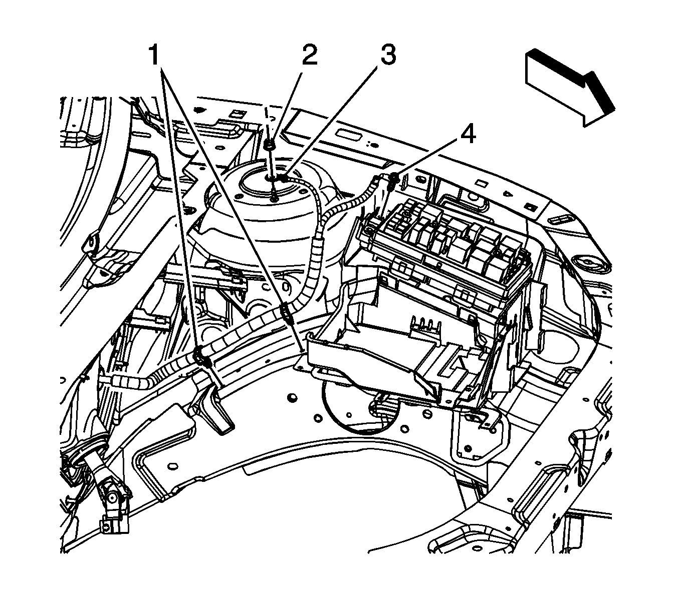
- Remove the stud nut (1) from the frame rail.
- Remove the mounting bolts (2).
- Remove the battery tray support.
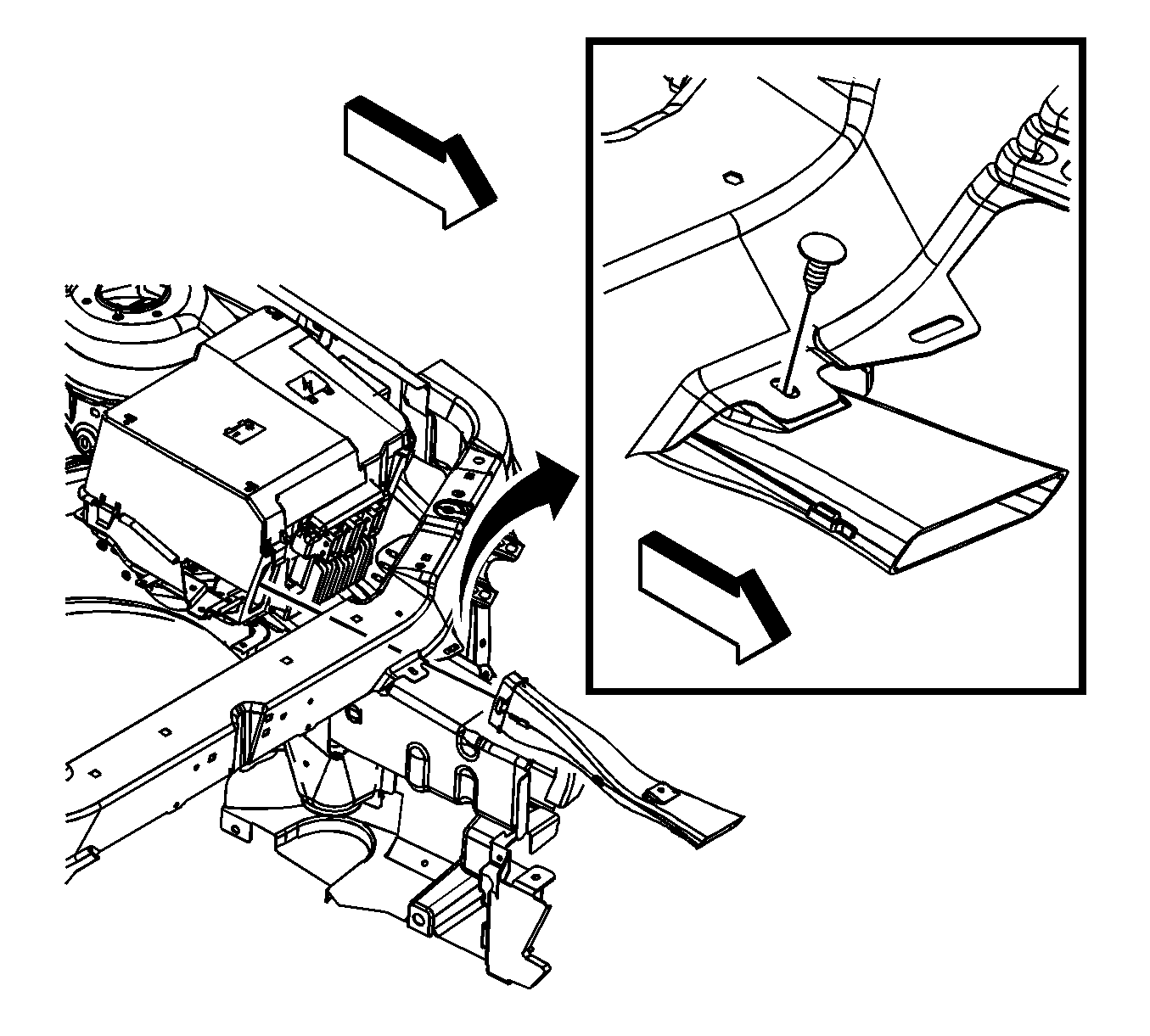
| • | Engine Control Module Replacement for the 2.4L engine |
| • | Engine Control Module Replacement for the 3.5L engine |
| • | Engine Control Module Replacement for the 3.6L engine |
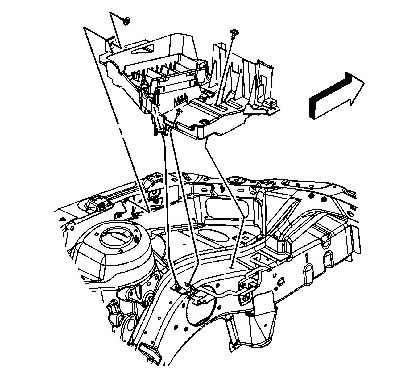
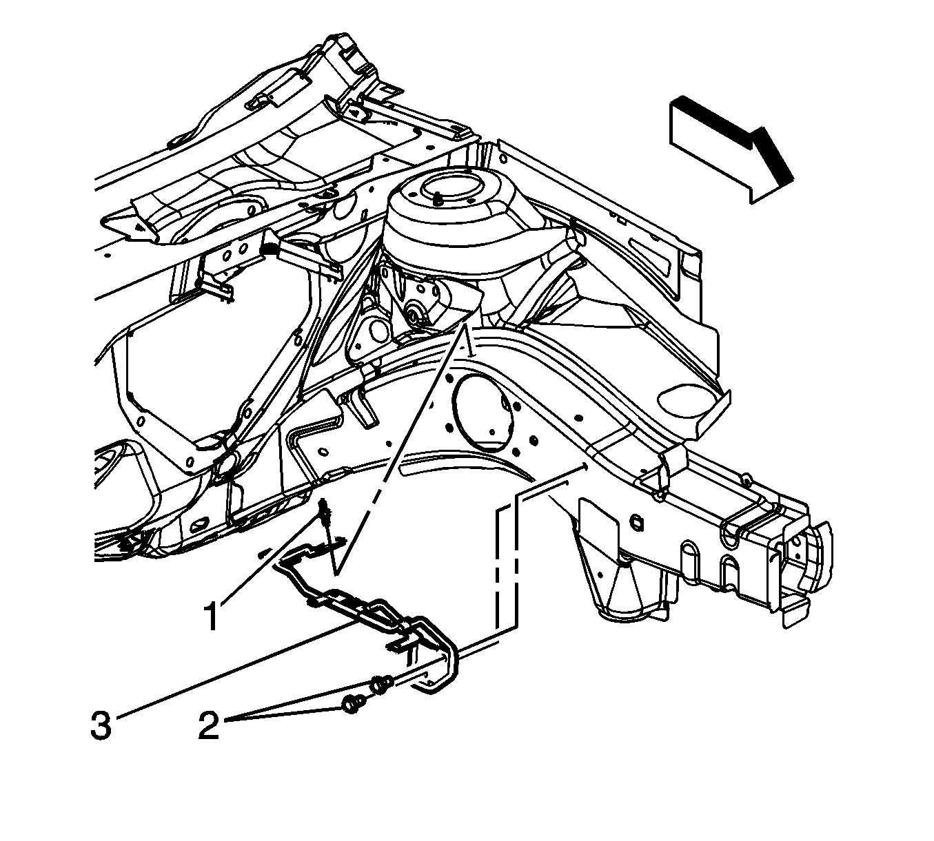
Note: The following service procedure are to be used if the battery tray support needs to be serviced.
Installation Procedure
- Position the battery tray support on the frame rail.
- Install the stud nut (1) and tighten to 25 N·m (18 lb ft).
- Install the mounting bolts (2) and tighten to 25 N·m (18 lb ft).
- Position the battery tray on the support.
- Install the mounting bolts for the battery tray. Tighten the nut to 16 N·m (12 lb ft).
- Install the air duct into the battery tray, if equipped.
- Install the air duct retainer, if equipped.
- Install the junction block. Refer to Underhood Electrical Center or Junction Block Replacement.
- Install the ECM. Refer to one of the following:
- Install the battery. Refer to Battery Replacement.

Caution: Refer to Fastener Caution in the Preface section.
Note: When tightening the mounting bolts and the nut stud, they must be tightened in sequence.


| • | Engine Control Module Replacement for the 2.4L engine |
| • | Engine Control Module Replacement for the 3.5L engine |
| • | Engine Control Module Replacement for the 3.6L engine |
Battery Tray Replacement LAT
Removal Procedure
- Remove the battery. Refer to Battery Replacement.
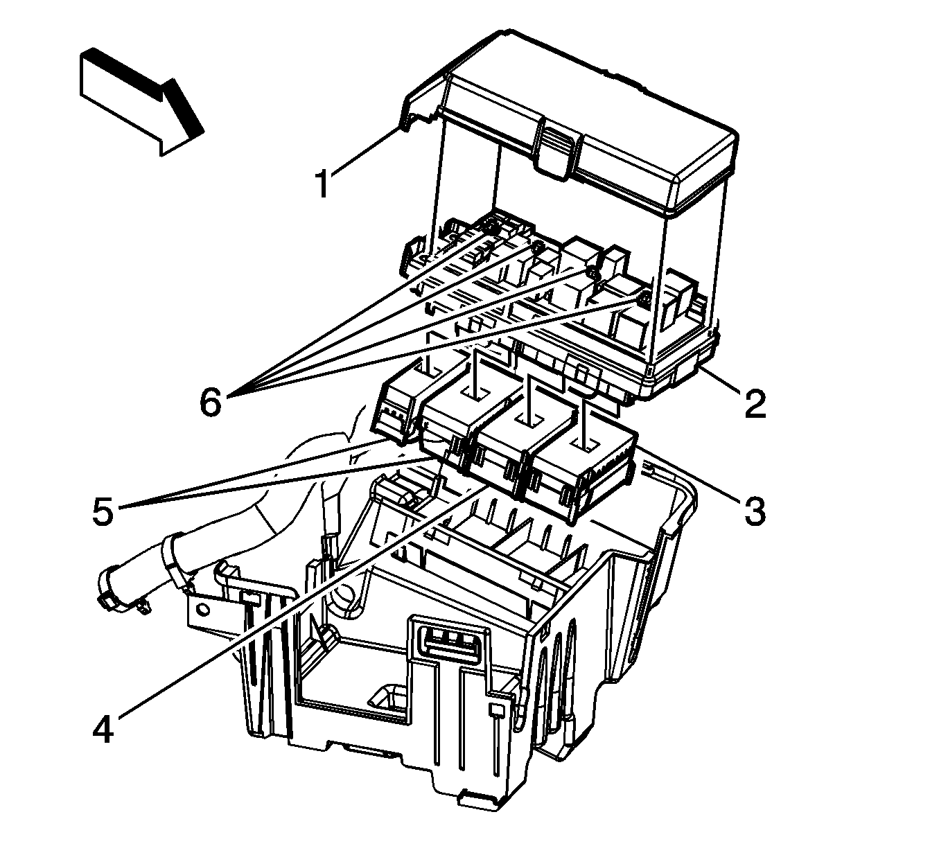
- Remove the underhood bussed electrical center (UBEC) cover.
- Loosen the integral bolt (5) on the positive battery cable lead (4) and remove the lead from the UBEC.
- Reposition the positive battery cable out of the way.
- Loosen the integral bolt (4) on the steering column harness package lead and remove the lead from the UBEC.
- Loosen the junction block bolts (6), once loose, tap the bolts once in order the disengage the bolts from the electrical connectors.
- Remove the junction block (2).
- Remove the engine wiring harness UBEC electrical connector (3) from the UBEC bracket and secure out of the way.
- Remove the forward lamp wiring harness UBEC electrical connector (4) from the UBEC bracket and secure out of the way.
- Remove the body wiring harness UBEC electrical connectors (5) from the UBEC bracket and secure out of the way.
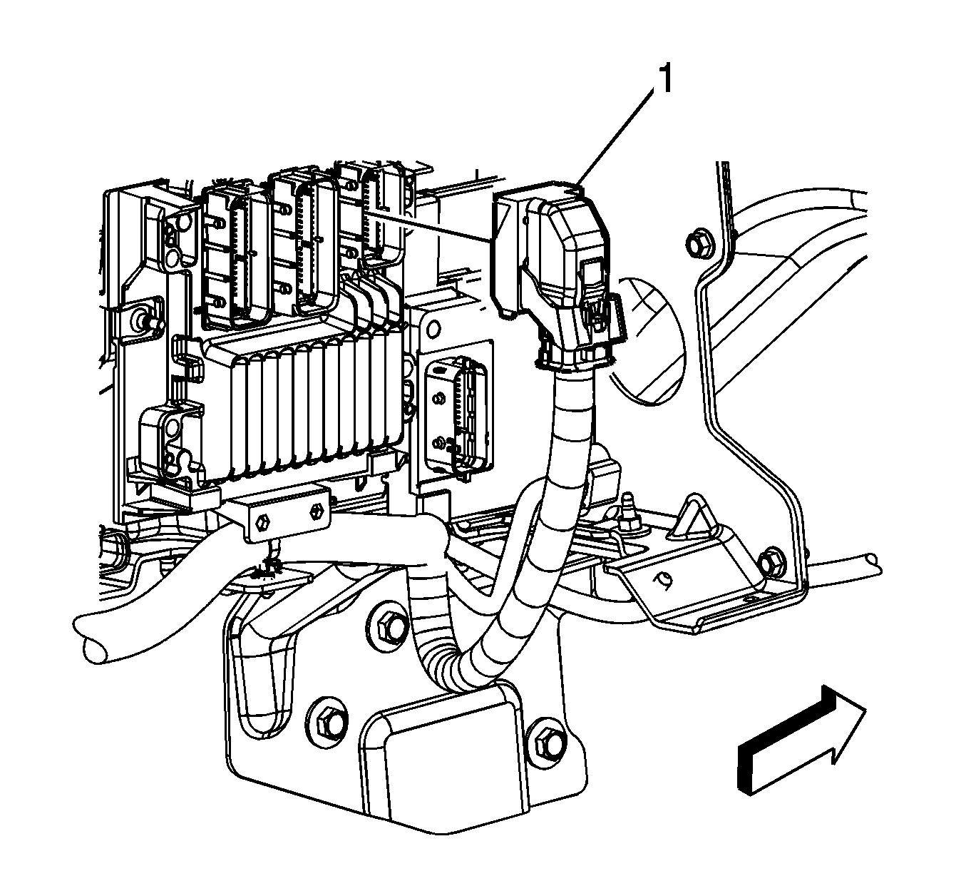
- Disconnect the body wiring harness electrical connector (1) from the engine control module (ECM).
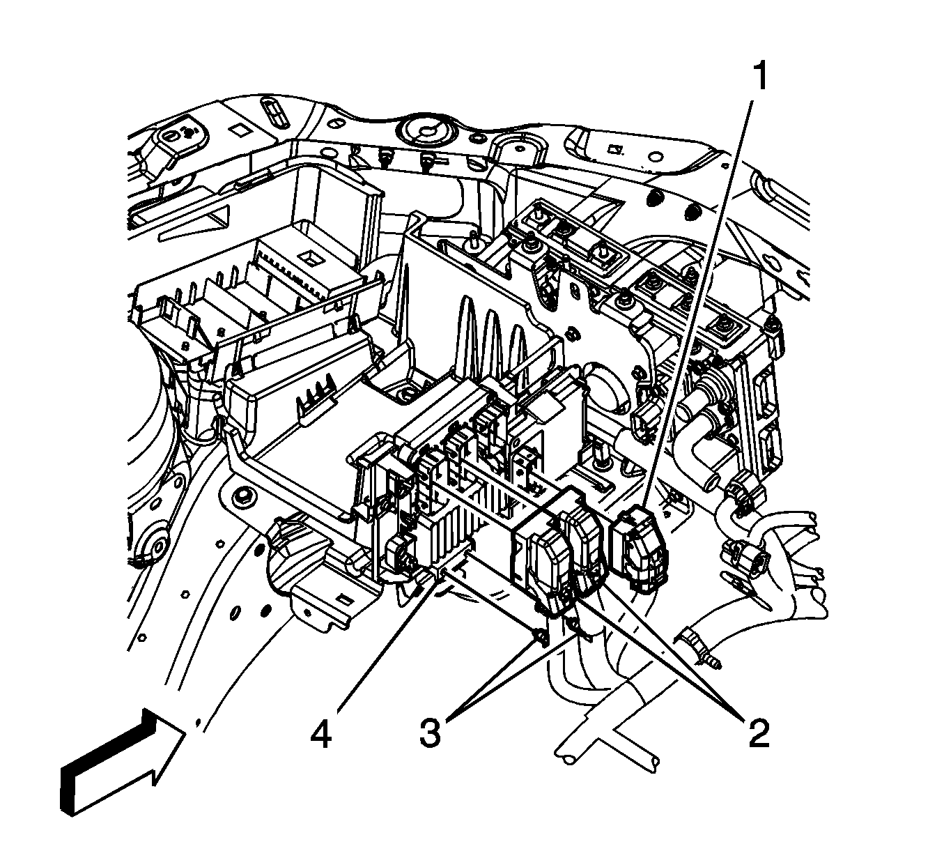
- Disconnect the engine wiring harness electrical connectors (2) from the ECM.
- Remove the engine wiring harness clips (3) from the ECM/transmission control module (TCM) bracket (4).
- Disconnect the engine wiring harness electrical connector (1) from the TCM.
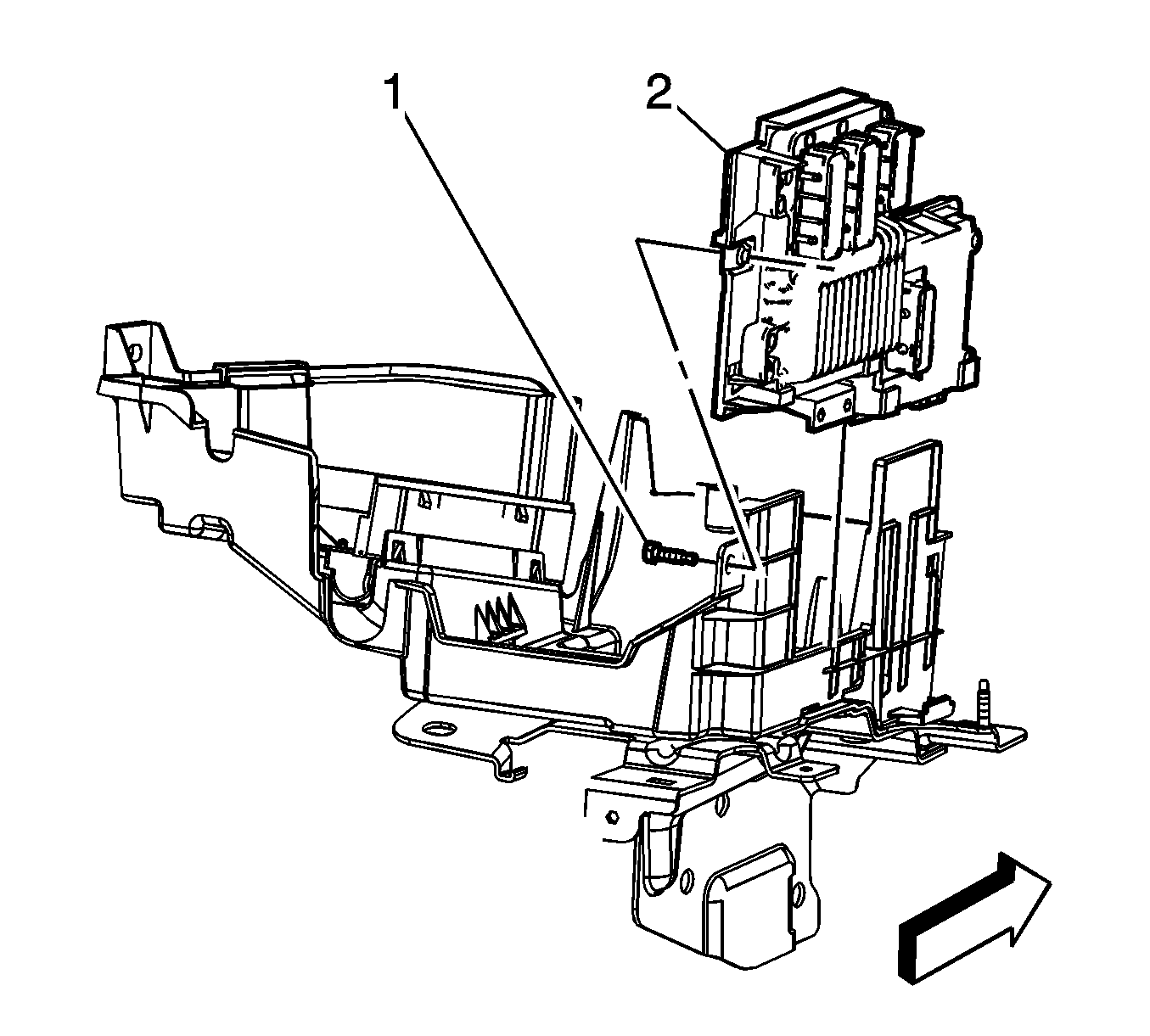
- Remove the ECM/TCM bracket bolt (1).
- Slide the ECM/TCM bracket up and remove the bracket (2) (With the ECM and TCM still attached) from the battery tray.
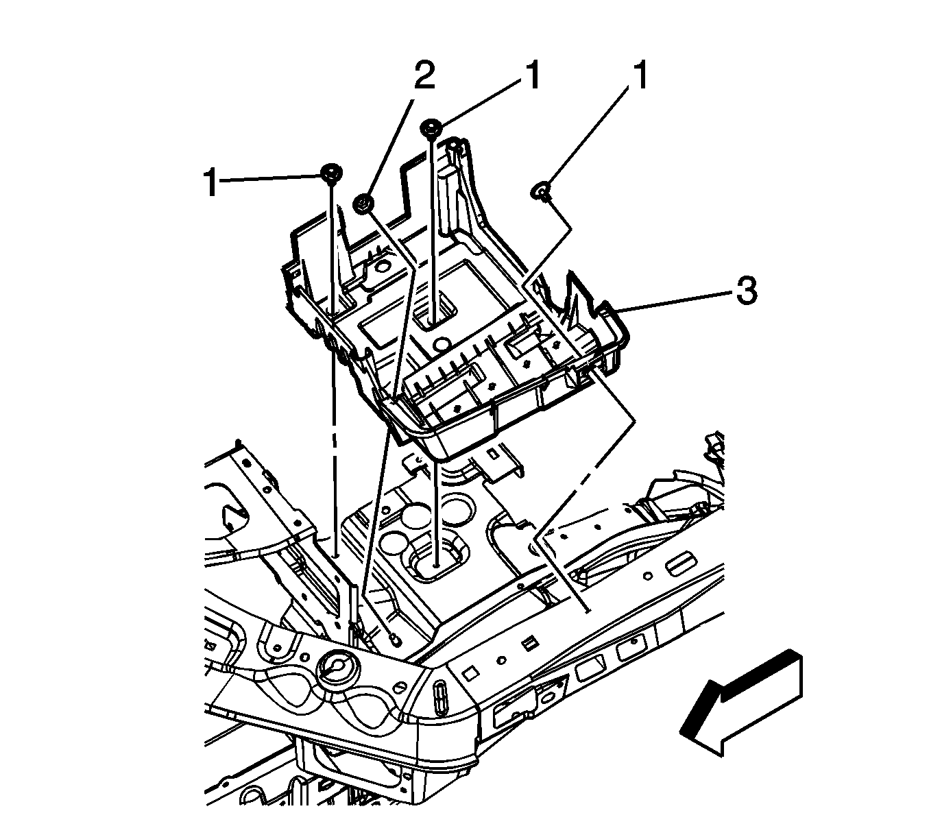
- Remove the battery tray bolts (1), nut (2), and battery tray (3).
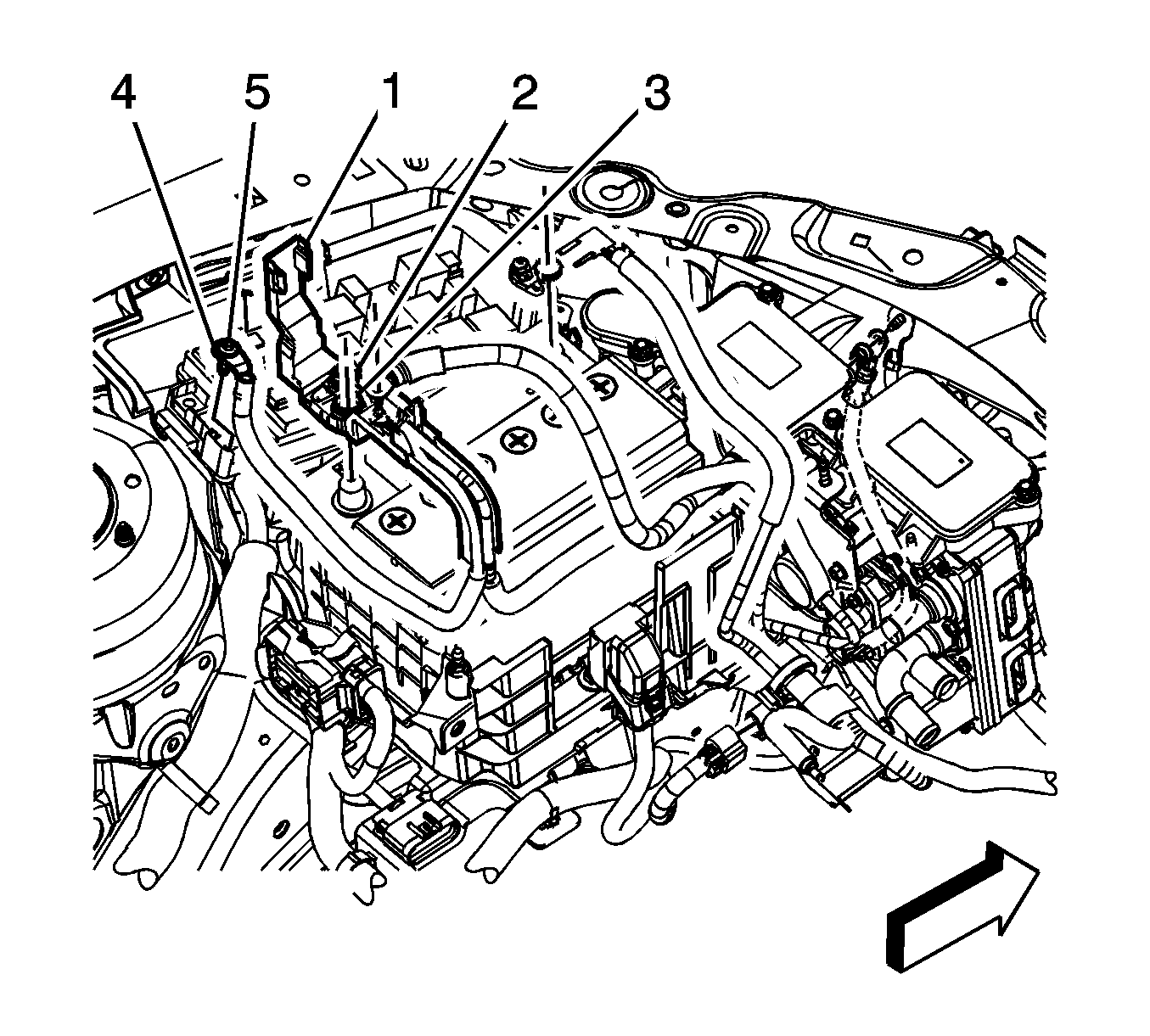
Note: Note the color and location of each electrical connector.
Installation Procedure
- Set the battery tray (3) into position and install the bolts (1), and nut (2). Tighten the bolts to 25 N·m (18 lb ft).
- Slide the ECM/TCM bracket (2) into position on the battery tray.
- Install the ECM/TCM bracket bolt (1) and tighten to 8 N·m (71 lb in).
- Connect the engine wiring harness electrical connector (1) to the TCM.
- Connect the engine wiring harness electrical connectors (2) to the ECM.
- Install the engine wiring harness clips (3) to the ECM/TCM bracket (4).
- Connect the body wiring harness electrical connector (1) to the ECM.
- Position the body wiring harness UBEC electrical connectors (5) to the UBEC bracket and snap into place.
- Position the forward lamp wiring harness UBEC electrical connector (4) to the UBEC bracket and snap into place.
- Position the engine wiring harness UBEC electrical connector (3) to the UBEC bracket and snap into place.
- Install junction block (2).
- Tighten the junction block bolts (6) until the bolts engage the electrical connectors, an audible click will be heard. Tighten the bolts to 4 N·m (35 lb in).
- Position the steering column harness package lead to the UBEC and tighten the integral bolt (4). Tighten the bolt to 5 N·m (44 lb in).
- Position the positive battery cable to the battery.
- Position positive battery cable lead (4) to the UBEC and tighten the integral bolt (5). Tighten the bolt to 5 N·m (44 lb in).
- Install the UBEC cover.
- Install the battery. Refer to Battery Replacement.
Caution: Refer to Fastener Caution in the Preface section.


