Removal Procedure
- Remove the knee bolster. Refer to Knee Bolster Replacement .
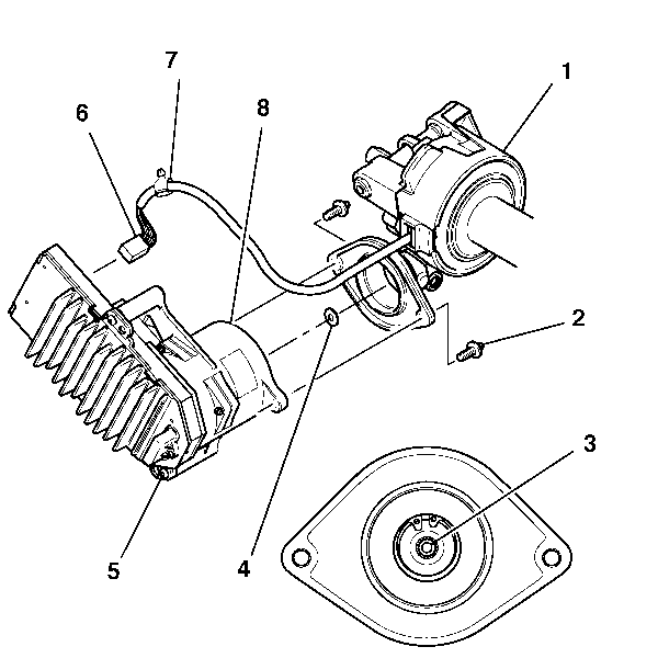
- Disconnect the sensor wire harness (6) from the motor/module assembly (5).
- Use needle nose pliers to remove the wire strap clip (7) from the motor/module assembly (5).
- Use a M6x1 head bit to remove the 2 motor/module assembly TORX® screws (2).
- Grasp the motor/module assembly (5) by the motor housing and remove it from the steering column (1) by pulling with an even tension.

Important: If replacing the motor/module assembly, you will need the sensor wire harness strap clip (7) for the new motor/module assembly installation.
If replacing the steering column, a new sensor wire harness strap clip (7) will come with the column service kit. Keep the existing wire strap clip attached to the steering column sensor wire harness (6).If replacing the motor/module assembly, remove the wire strap clip (7) from the sensor wire harness (6).
If replacing the steering column, keep the wire harness strap clip (7) attached to the sensor wire harness (6).
Discard the screws.
Important: Once the motor/module assembly has been removed, inspect the steering column assist mechanism input shaft (3) for the rotor isolator bumper (4). If present, remove and insert back into the rotor isolator (8) in the motor/module assembly (5).
The assist mechanism housing must be free of any type of debris. Remove any loose debris from the steering column assist mechanism housing, but do NOT remove the remaining grease on the steering column assist mechanism input shaft (3).Installation Procedure
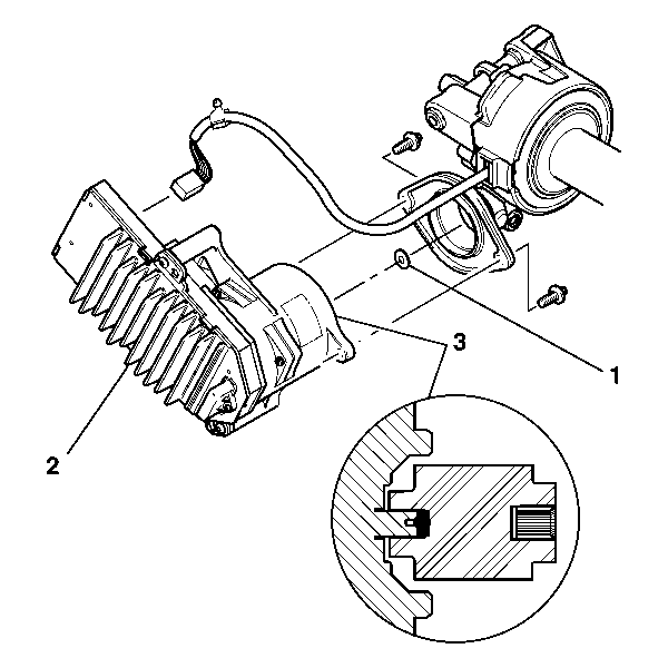
- Fit the motor/module assembly rotor isolator over the steering column assist mechanism input shaft.
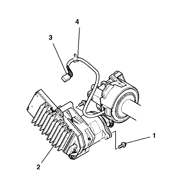
- Use a M6x1 TORX® head bit to attach the motor/module assembly (2) to the steering column with the 2 new TORX® bolts (1).
- Connect the sensor wire harness (3) to the motor/module assembly (2).
- Install the sensor wire harness strap clip (4) into the motor/module assembly (2).
- Install the knee bolster. Refer to Knee Bolster Replacement .
- Perform the control module setup. Refer to Control Module References for programming and setup information.

Notice: Do NOT allow the wiring harness to be pinched between the motor/module assembly and the steering column during installation. A pinched harness will cause diagnostic trouble codes to be set and may require replacement of the steering column.
Important: Before installing the motor/module assembly (2), verify the rotor isolator bumper (1) is installed into the rotor isolator (3) in the motor/module assembly (2).
Notice: Refer to Fastener Notice in the Preface section.

Tighten
Tighten the steering column bolts to 9 N·m (80 lb in).
