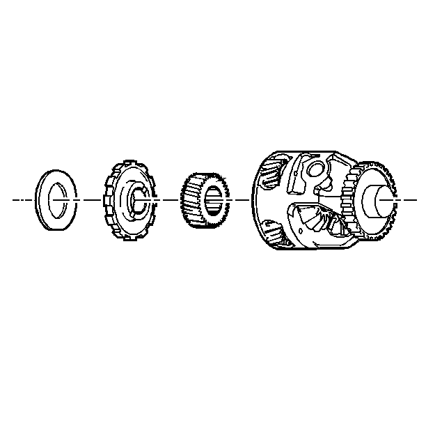
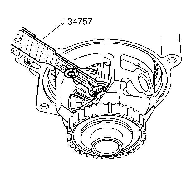
Removal Procedure
- J 28467-360 Engine
Support Fixture
- J 28467-90 Engine
Support Fixture Adapter
- J 36462 Engine
Support Adapter Leg
- Disconnect the electrical cooling fans. Refer to
Electric Cooling Fan
in Engine Cooling.
- Remove the accessory drive belt.
- Drain the cooling system. Refer to
Cooling System Draining and Filling
in Engine Cooling.
- Remove the heater hose pipe at the intake manifold.
- Position the J 28467-360
, J 28467-90
, and J 36462
.
- Raise and suitably support the vehicle. Refer to General Vehicle
Lifting and Jacking in General Information.
- Refer to Wheel Removal in Tires and Wheels in order to remove
the front tires.
- Remove the upper half of the right engine splash shield.
- Remove the catalytic converter. Refer to
Catalytic Converter Replacement
in Exhaust System.
- Remove the frame. Refer to Frame in Body Dimensions, Frame and
Underbody.
- Lower the vehicle.
- Lower the powertrain 3 inches using an engine support fixture.
- Remove both of the drive axles.
- Support the drive axles to the body. Refer to Drive Axle in Drive
Axle On-Vehicle Service.
- Remove the case extension housing. Refer to
Case Extension Replacement
.
- Remove the output shaft snap ring. Refer to the Output Shaft Disassemble
.
- Remove the carrier.
- Remove the differential.

- Disassemble the following components, if necessary:
| 19.1. | The parking system. Refer to Park System Components Disassemble
. |
| 19.2. | The sun gear and planetary gear. Refer to Reaction Sun Gear and Manual 2-1 Band Disassemble
. |
| 19.3. | The differential pinion gears and side gears. Refer to Differential Carrier Internal Gear Disassemble
. |
Installation Procedure
- J 28467-360 Engine
Support Fixture
- J 28467-90 Engine
Support Fixture Adapter
- J 36462 Engine
Support Adapter Leg

- Assemble the following components, if necessary:
| 1.1. | The parking system. Refer to Park System Components Assemble
. |
| 1.2. | The sun and planetary gears. Refer to Reaction Sun Gear and Drum Assemble
. |
| 1.3. | The differential pinion and side gears. Refer to Differential Carrier Internal Gear Assemble
. |
- Install the carrier.
- Install the differential.

- Install the output shaft snap ring.
- Install the case extension housing. Refer to
Case Extension Replacement
.
- Measure the final drive end play. Refer to the
Differential Carrier End Play Check
.
- Remove both drive axles. Refer to Drive Axle in Drive Axle On-Vehicle
Service.
- Raise the powertrain 3 inches using an engine support fixture.
- Raise and suitably support the vehicle. Refer to General Vehicle
Lifting and Jacking in General Information.
- Install the frame. Refer to Frame in Body Dimensions,
Frame and Underbody.
- Install the catalytic converter. Refer to
Catalytic Converter Replacement
in Exhaust System.
- Install the upper half of the right engine splash shield.
- Refer to Wheel Removal in Tires and Wheels in order to install
the front tire.
- Lower the vehicle.
- Remove J 28467-360
,
and J 28467-90
and the J 36462
.
- Install the heater hose pipe at the intake manifold.
- Refill the cooling system. Refer to
Cooling System Draining and Filling
in Engine Cooling.
- Install the accessory drive belt.
- Connect the electric cooling fans. Refer to
Electric Cooling Fan
in Engine Cooling.


