Removal Procedure
GM replacement brake or equivalent lining material is recommended for
all GM vehicles in order to maintain the balance between front and rear brake
performance. GM replacement brake parts have been carefully selected in order
to provide the proper brake balance for purposes of both stopping distance
and control over the full range of operation conditions. Installation of
front or rear brake pad material with performance different than that of
the GM replacement parts recommended for this vehicle can change the intended
brake balance of this vehicle.
- Remove two-thirds of the brake fluid from the master cylinder.
- Raise the vehicle and suitably support. Refer to
Lifting and Jacking the Vehicle
- Mark the relationship of the wheel to the hub.
- Remove the tire and the wheel. Refer to
Tire and Wheel Removal and Installation
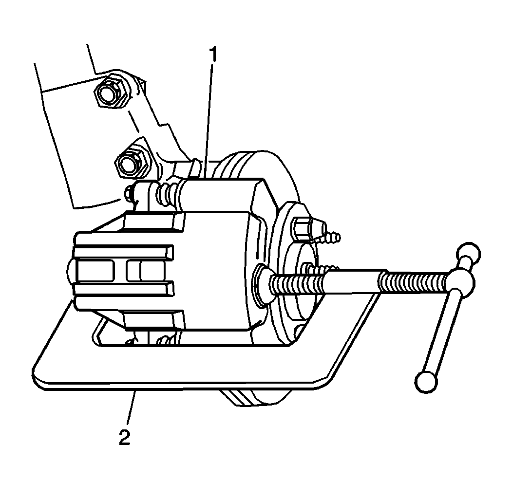
- Push pistons onto the
caliper bores in order to provide clearance between the pads and the rotor.
| 5.1. | Install a large C-clamp (2) over the top of the caliper housing
(1) and against the back of the outboard pad. |
| 5.2. | Slowly tighten the C-clamp until the pistons push into the caliper
bores enough to slide the caliper off the rotor. |
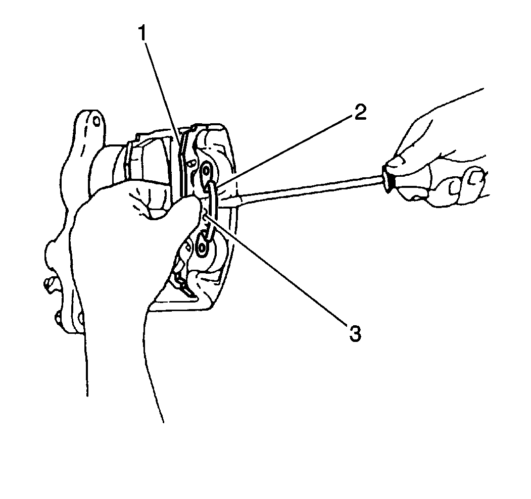
- Remove the outboard brake
pad (1).
Use a screwdriver to lift up the outboard pad retaining spring (2) so
that it will clear the caliper center lug (3).
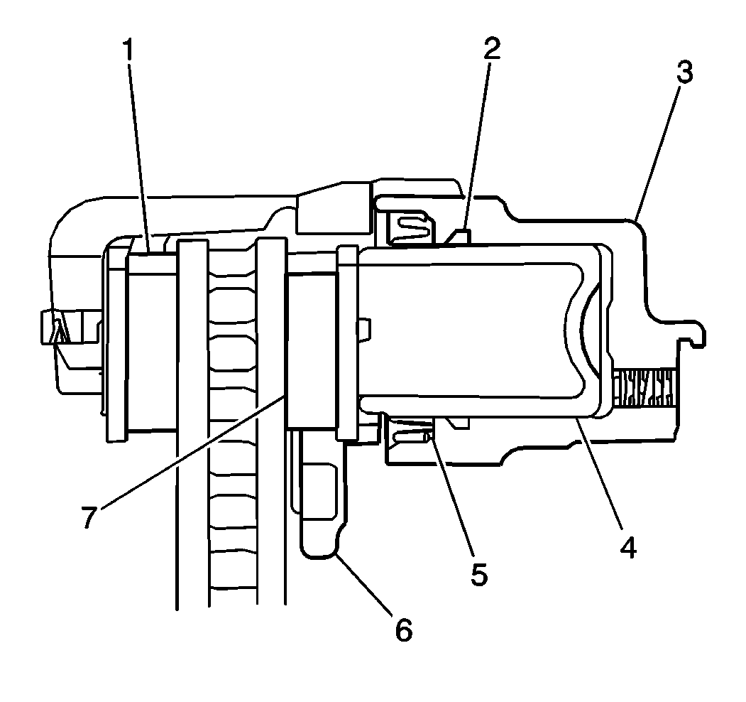
- Unsnap the pad springs
from the piston ID's.
- Remove the inboard bake pad (7).
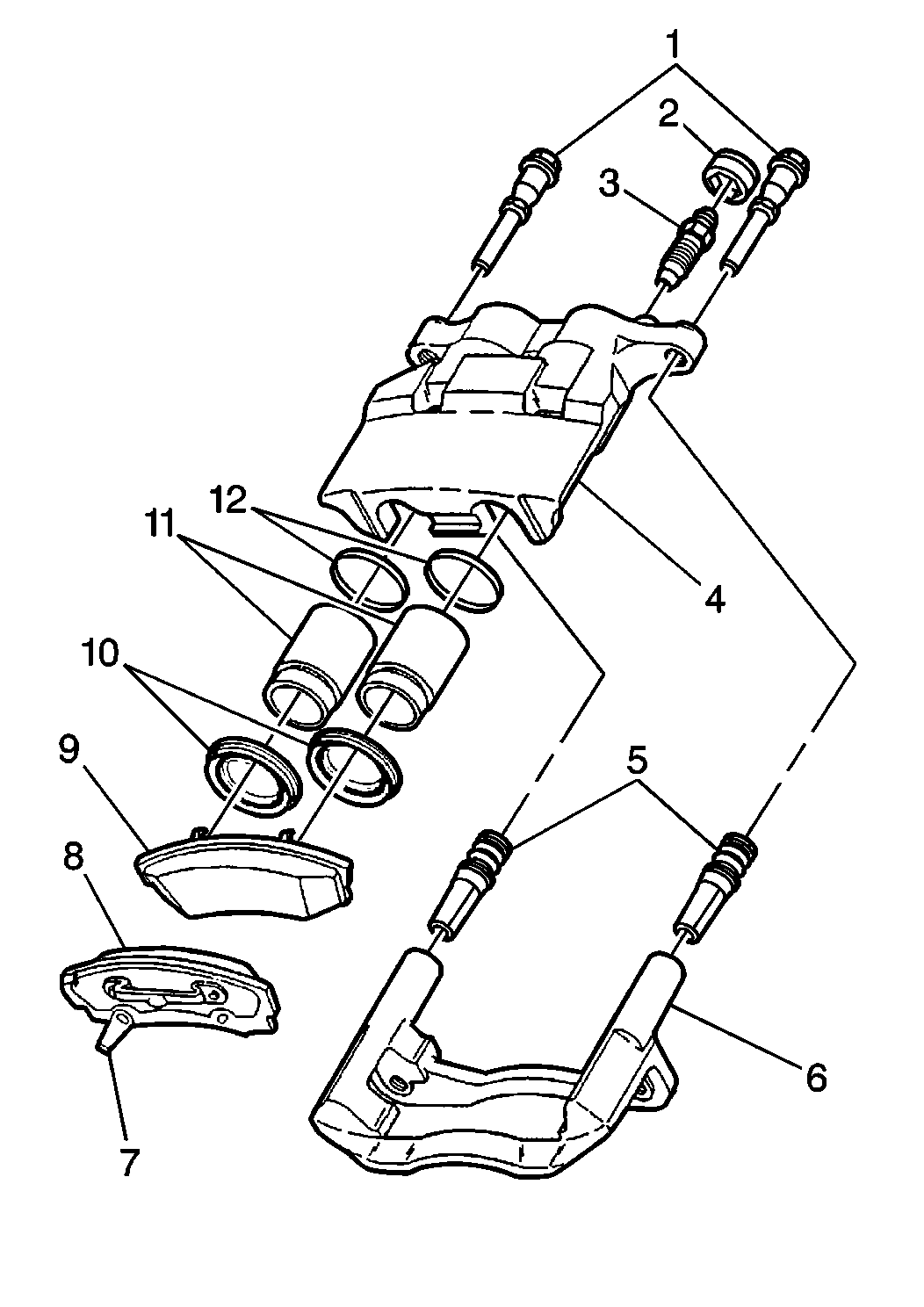
- Inspect the following
parts for cuts, tears, or deterioration. Replace any damaged parts.
- Inspect the slide pin bolts (1) for corrosion or damage. If corrosion
is found, use new parts, including bushings, when installing the caliper.
Do not attempt to polish away corrosion.
Installation Procedure
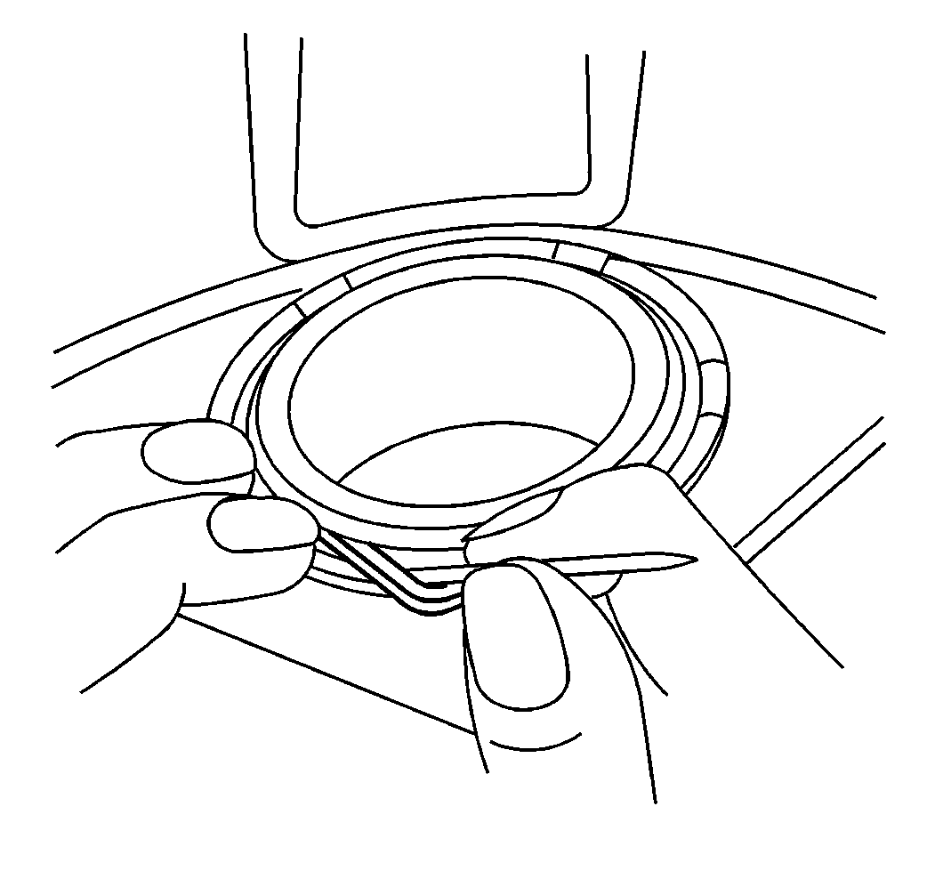
Important: Lift the inner edge of the caliper boots next to the pistons. Press
out any trapped air. The boots must lay flat below the level of the piston
faces.
- If installing new brake
pads, bottom the pistons into the caliper bore. Use a C-clamp and a metal
plate or wooden block in order to clamp both of the pistons at the same time.
Do not damage the pistons or the caliper boots.

- Install the inboard brake
pad (9) by snapping the pad retainer springs into the piston ID's. The pad
retainer springs are already staked to the inboard pad.
| • | Verify that both tangs of the retainer springs are installed inside
the piston ID. |
| • | The pad must lay flat against the pistons. |
| • | After installing the brake pads, verify that the caliper boots
are not touching the pads. If there is contact, remove the brake pads and
re-seat or re-position the boots. |

- Install the outboard brake
pads (1) by snapping the outboard pad retaining springs (2) over the caliper
center lug (3) and into the housing slot.
| • | The wear sensor should be at the trailing edge of the pad during
forward wheel rotation. |
| • | The back of the pad must lay flat against the caliper. |
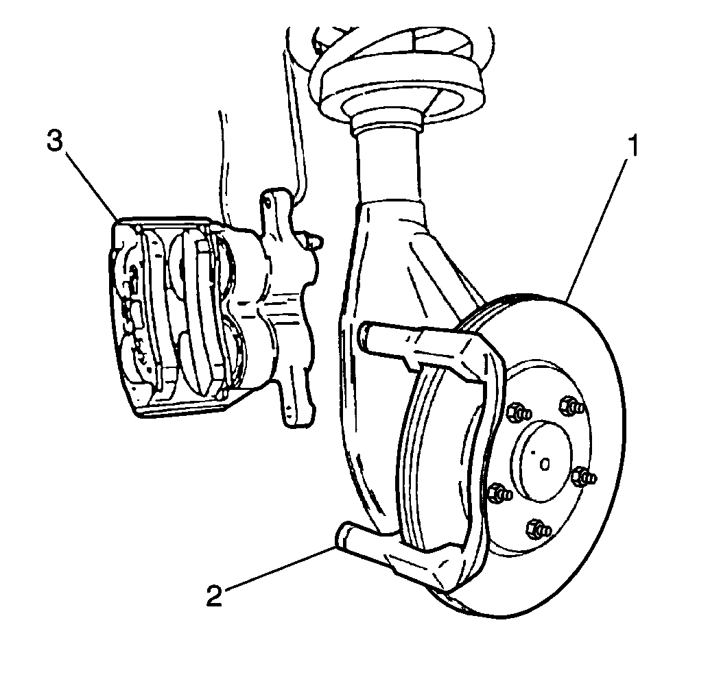
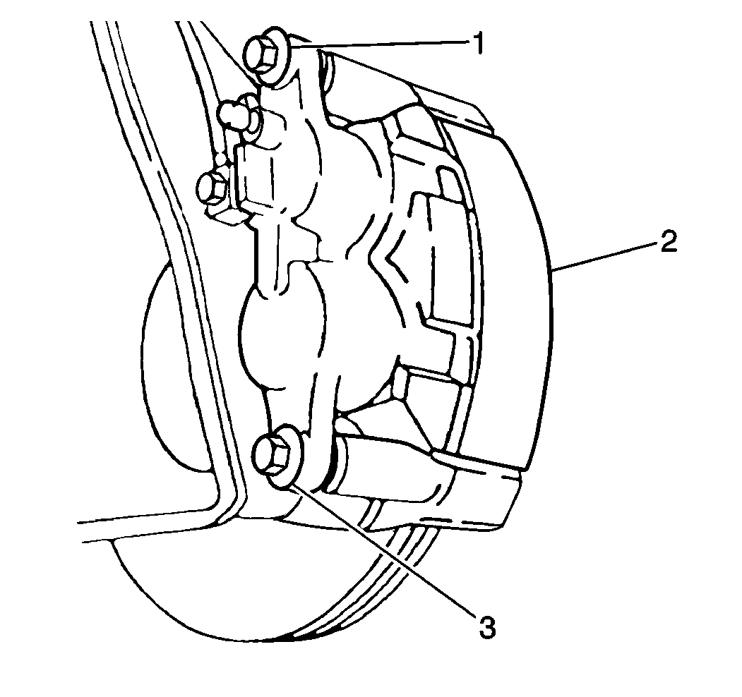
- Install the caliper (3)
over the rotor (1) and the caliper mounting bracket (2).
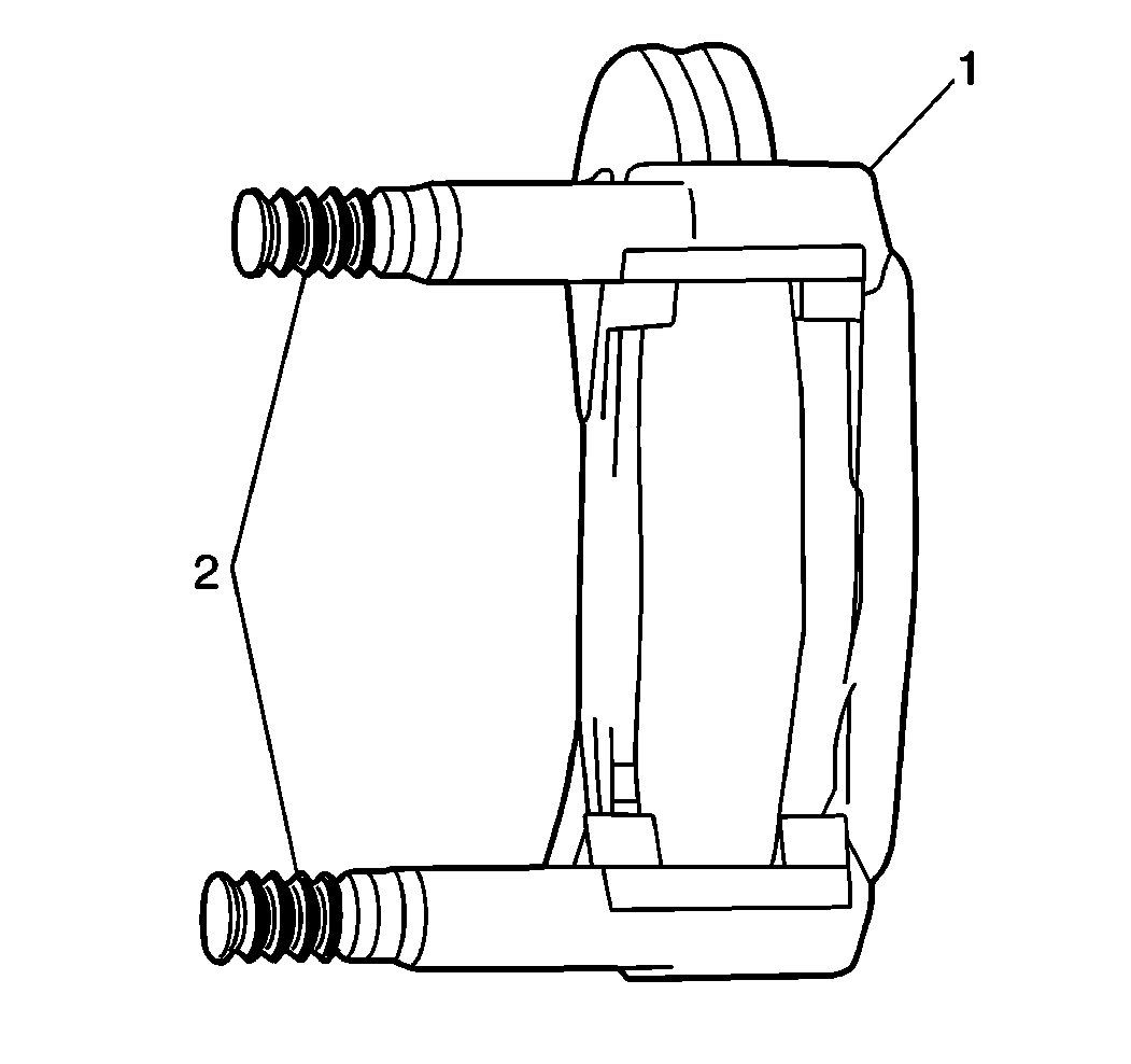
- Verify that the bushings
(2) are in place.
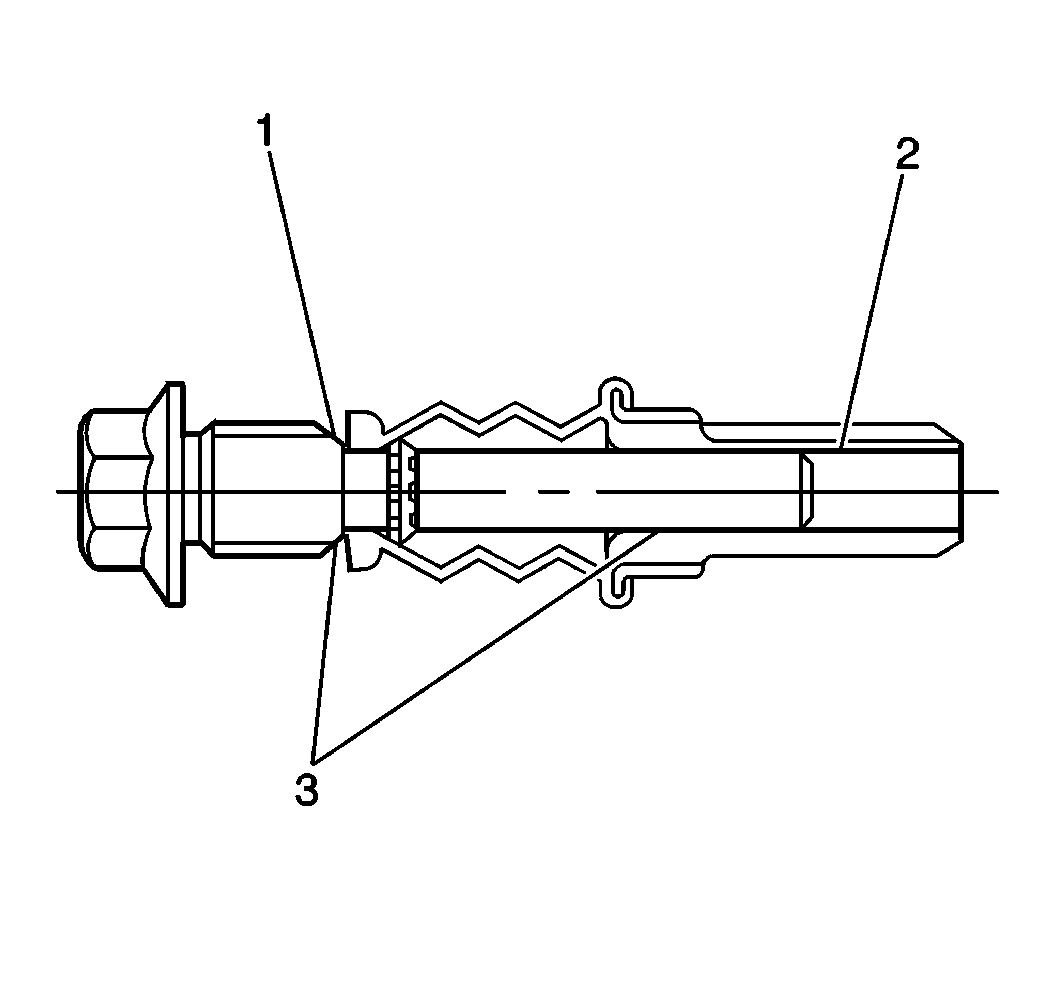
- Lubricate the caliper
slide pin bolts (1) using silicone grease.
Do not lubricate the threads.
- Lubricate the two rubber bushings in the caliper mounting bracket
using silicon grease.
Notice: Use the correct fastener in the correct location. Replacement fasteners
must be the correct part number for that application. Fasteners requiring
replacement or fasteners requiring the use of thread locking compound or sealant
are identified in the service procedure. Do not use paints, lubricants, or
corrosion inhibitors on fasteners or fastener joint surfaces unless specified.
These coatings affect fastener torque and joint clamping force and may damage
the fastener. Use the correct tightening sequence and specifications when
installing fasteners in order to avoid damage to parts and systems.
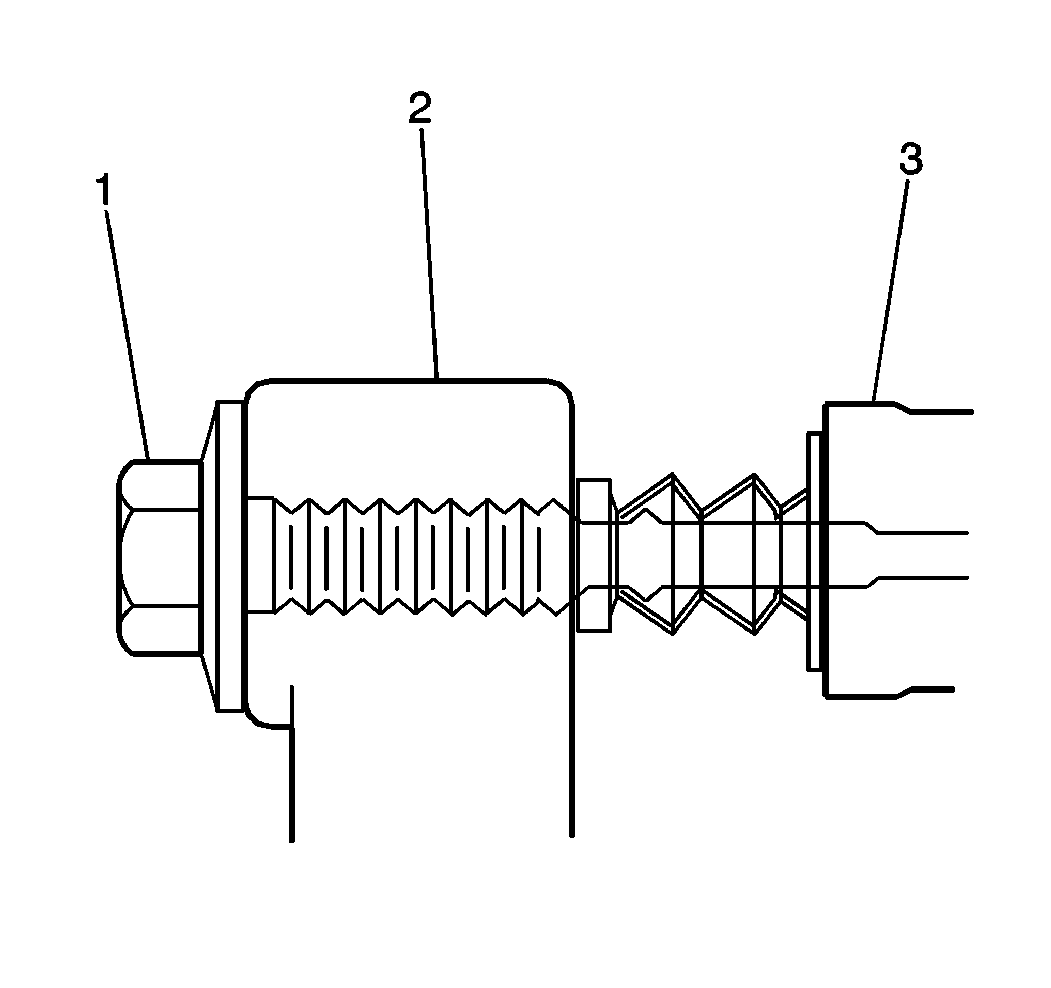
- Install the caliper
slide pin bolts (1).
Using a screwdriver, push the pin boot over the shoulder of the pin
bolt. The pin boot must be securely in the grove of the pin bolt.
Tighten
Tighten the slide pin bolts to 108 N·m (80 lb ft).
- Remove the wheel nuts
securing the rotor to the hub.
- Install the tires and the wheels. Refer to
Tire and Wheel Removal and Installation
- Lower the vehicle.
- Fill the master cylinder to the proper level with clean brake
fluid. Refer to
Master Cylinder Reservoir Filling
- Apply approximately 778 N (175 lb) of force three
times to the brake pedal to seat the pads.
- Burnish the pads and the rotors. Refer to
Brake Pad and Rotor Burnishing


