Disc Brakes System Description Front

Important:
• Replace all components included in repair kits used to service
this caliper. • Lubricate rubber parts with clean brake fluid in order to ease
assembly. • Do not use lubricated compressed air on brakes. Doing so may damage
the rubber components. • Bleed the entire brake system whenever you remove any hydraulic
component. • Replace brake pads in axle sets only. • The specified torque values are for dry, non-lubricated fasteners. • Perform service operations on a clean bench.
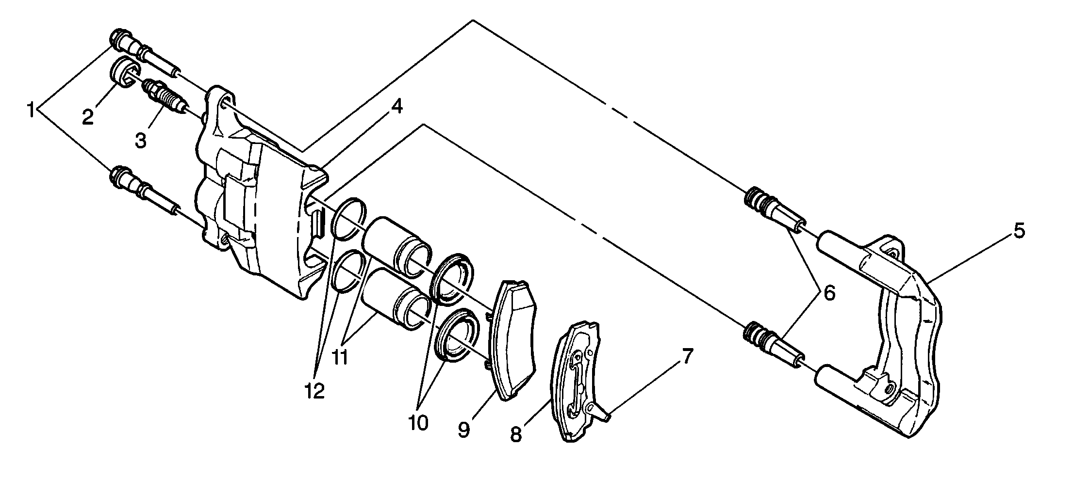
The caliper (4) used on this vehicle has interconnected dual bores. The caliper is mounted to the support bracket (5) with two mounting bolts (1). Applying the brake pedal creates hydraulic pressure. The caliper converts this hydraulic pressure to a stopping force. This force acts equally against the pistons (11) and the bottom of the caliper bores in order to move the pistons outward and to move (slide) the caliper inward. This results in a clamping action on the rotor. The clamping action forces the pads (9, 7) against the rotor, creating friction in order to stop the vehicle.
Do not refinish the brake rotors when performing routine brake maintenance, such as replacing worn disc brake pads. Refinish a rotor only under the following circumstances:
| • | There is a complaint of brake pulsation. |
| • | There is scoring greater than 1.5 mm (0.060 in). |
All brake rotors have a minimum thickness dimension cast into them. This dimension is a minimum wear dimension, not a refinishing dimension. Do not use a brake rotor that, after refinishing, will not meet the specifications shown on the rotor. Always use a new rotor.
Accurate control of the rotor tolerance is necessary for proper performance of the disc brakes. Use only precision equipment in order to machine the rotor. Service the machining equipment on a regular basis. Follow the manufacturer's recommended maintenance procedure.
The following tool accessories must be in good condition when refinishing rotors:
| • | Attaching adapters |
| • | Tool holders |
| • | Vibration dampeners |
| • | Tool bits |
Always use sharp cutting tools and bits. Use only replacement cutting bits recommended by the equipment manufacturer. Dull or worn tools leave a poor surface finish which will affect braking performance. Always use vibration dampening attachments when refinishing braking surfaces. The attachments eliminate tool chatter and will result in a better surface finish. Ensure that the adapters are clean and free of nicks.
For best results, use an on-vehicle brake lathe whenever you are refinishing a rotor in order to correct a problem with brake pulsation. Follow the equipment manufacturer's recommended specifications and procedure.
Operation of Disc Brakes
When the brakes are applied, the fluid pressure that is behind the caliper piston increases. Pressure is exerted equally against the bottom of the following components:
| • | The piston(s) |
| • | The piston bore(s) |
The pressure that is applied to the piston is transmitted to the inner pad. The pressure forces the pad against the inner rotor surface. The pressure that is applied to the bottom of the piston bore(s) forces the caliper to slide onto the mounting bolts, toward the center of the vehicle. Since the caliper is one piece, the movement causes the outer section of the caliper to apply pressure against the back of the outer pad. This forces the pad against the outer rotor surface. As line pressure builds, the pads are pressed against the rotor surfaces with increased force, bringing the vehicle to a stop.
When the brake pedal releases, the line pressure releases. The seal and the seal groove cause the piston to retract slightly. This results in less drag on the rotor by both pads. Outward movement of the piston and inward movement of the caliper automatically compensate for pad wear. As the pads wear, the increased area behind the piston fills with brake fluid from the master cylinder reservoir.
Disc Brakes System Description Rear

Important:
• Replace all components included in repair kits used to service
this caliper. • Lubricate rubber parts with clean brake fluid in order to ease
assembly. • Do not use lubricated compressed air on brakes. Doing so may damage
the rubber components. • Bleed the entire brake system whenever you remove any hydraulic
component. • Replace brake pads in axle sets only. • The specified torque values are for dry, non-lubricated fasteners. • Perform service operations on a clean bench.
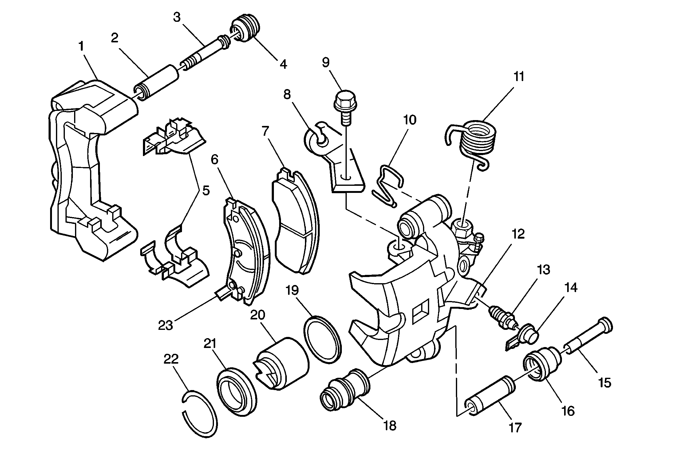
The caliper (12) used on this vehicle has a single bore. The caliper is mounted to the support bracket (1) with two mounting bolts. Applying the brake pedal creates hydraulic pressure. The caliper converts this hydraulic pressure to a stopping force. This force acts equally against the piston (20) and the bottom of the caliper bore in order to move the piston outward and to move (slide) the caliper inward. This results in a clamping action on the rotor. This clamping action forces the pads (6, 7) against the rotor, creating friction in order to stop the vehicle.
When the parking brake is applied, the external caliper parking brake lever moves and rotates a spindle within the caliper housing. As the spindle rotates, a connecting rod is pushed against an internal adjusting screw which is threaded into a sleeve nut (cone) in the piston. This causes the piston to move outward bringing the inboard brake pads against the rotor. As the inboard brake pad contacts the rotor, a reaction force causes the caliper housing to slide inward pressing the outboard brake pads against the rotor.
The piston contains a self-adjusting mechanism in order to keep the parking brake in proper adjustment. As the pads are worn, the piston moves through the seal in order to maintain proper pads to rotor clearance. The park brake adjusts to the proper clearances through an internal sleeve nut that rotates and moves as one unit with the piston.
Do not refinish brake rotors when performing routine brake maintenance, such as replacing worn disc brake pads. Refinish a rotor only under the following circumstances:
| • | There is a complaint of brake pulsation. |
| • | There is scoring greater than 1.5 mm (0.60 in). |
All brake rotors have a minimum thickness dimension cast into them. This dimension is a minimum wear dimension, not a refinishing dimension. Do not use a brake rotor that, after refinishing, will not meet the specifications shown on the rotor. Always use a new rotor.
Accurate control of the rotor tolerance is necessary for proper performance of the disc brakes. Use only precision equipment in order to machine the rotor. Service the machining equipment on a regular basis. Follow the manufacturer's recommended maintenance procedure.
The following tool accessories must be in good condition when refinishing rotors:
| • | Attaching adapters |
| • | Tool holders |
| • | Vibration dampeners |
| • | Tool bits |
Always use sharp cutting tools and bits. Use only replacement cutting bits recommended by the equipment manufacturer. Dull or worn tools leave a poor surface finish which will affect braking performance. Always use vibration dampening attachments when refinishing braking surfaces. The attachments eliminate tool chatter and will result in a better surface finish. Ensure that the adapters are clean and free of nicks.
For best results, use an on-vehicle brake lathe whenever you are refinishing a rotor in order to correct a problem with brake pulsation. Follow the equipment manufacturer's recommended specifications and procedures.
Operation of Disc Brakes
When the brakes are applied, the fluid pressure that is behind the caliper piston increases. Pressure is exerted equally against the bottom of the following components:
| • | The piston(s) |
| • | The piston bore(s) |
The pressure that is applied to the piston is transmitted to the inner pad. The pressure forces the pad against the inner rotor surface. The pressure that is applied to the bottom of the piston bore(s) forces the caliper to slide onto the mounting bolts, toward the center of the vehicle. Since the caliper is one piece, the movement causes the outer section of the caliper to apply pressure against the back of the outer pad. This forces the pad against the outer rotor surface. As line pressure builds, the pads are pressed against the rotor surfaces with increased force, bringing the vehicle to a stop.
When the brake pedal releases, the line pressure releases. The seal and the seal groove cause the piston to retract slightly. This results in less drag on the rotor by both pads. Outward movement of the piston and inward movement of the caliper automatically compensate for pad wear. As the pads wear, the increased area behind the piston fills with brake fluid from the master cylinder reservoir.
