Removal Procedure
Caution: Do not move the vehicle until a firm brake pedal is obtained. Failure
to obtain a firm pedal before moving vehicle may result in personal injury.
Notice: Do not allow calipers to hang from the flexible hoses. Doing so can
damage the hoses.
- Remove two-thirds of the brake fluid from the master cylinder.
- Raise and suitably support the vehicle. Refer to
Lifting and Jacking the Vehicle
in General information.
- Mark the relationship of the wheel to the hub and the bearing.
- Remove the tire and the wheel. Refer to
Tire and Wheel Removal and Installation
in Tire and
Wheels.
- Install two wheel nuts in order to retain the rotor.

- If the caliper will be
removed completely from the vehicle for unit repair, complete the following
steps:
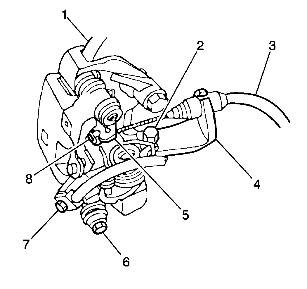
| • | Remove the brake hose (7) from the caliper. |
| • | Plug the openings in the caliper and the brake hose in order to prevent
fluid loss and contamination. |
| • | Remove the parking brake cable (3) from the parking brake lever
(5). |
| • | Lift up one end of the cable spring clip (8) in order to free the end
of the cable from the lever. |
- Remove the bolt (2) and washer that attach the cable support bracket
(4) to the caliper.
- Remove the sleeve bolts (6).

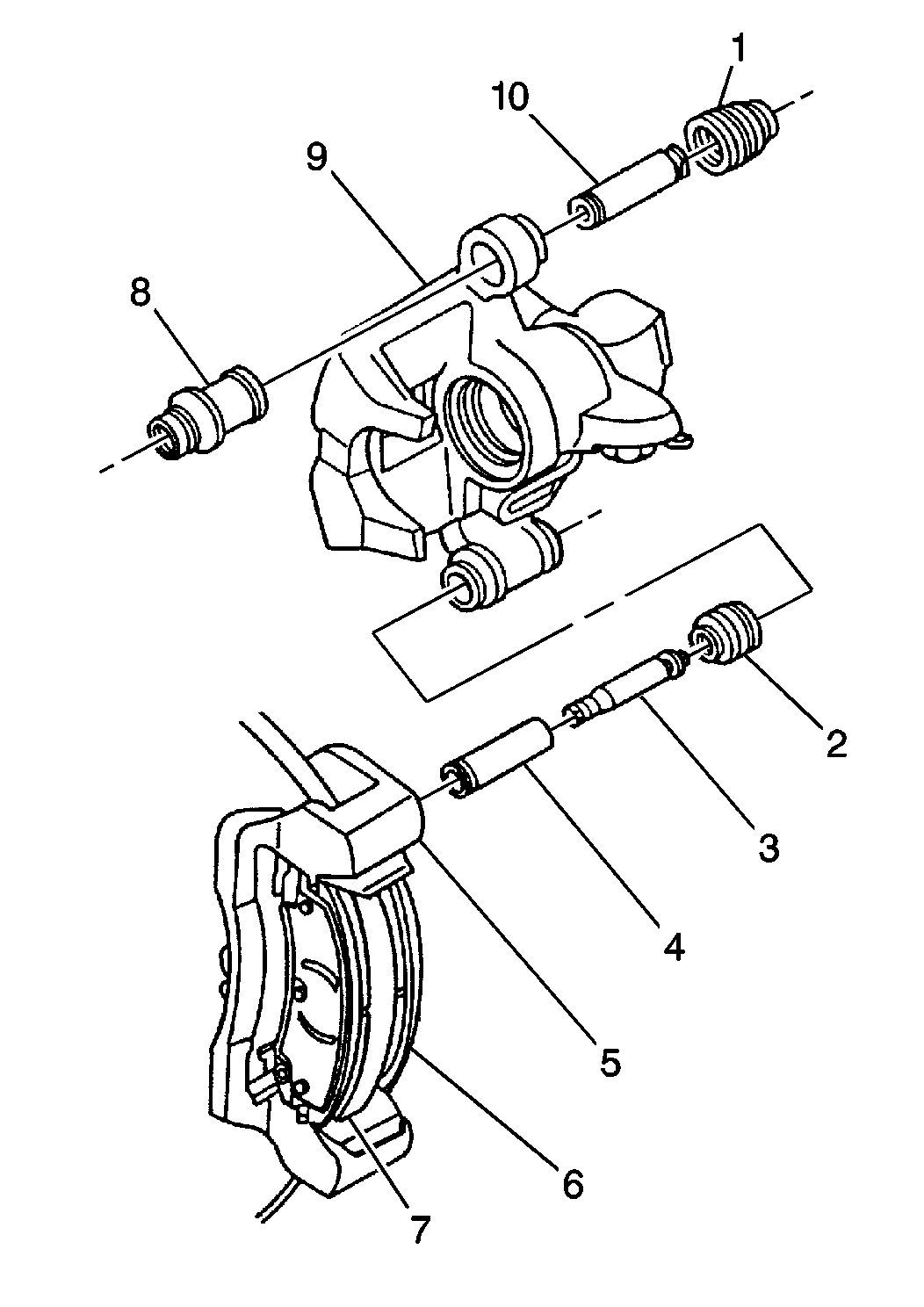
- Remove the caliper (9)
using the following steps:
| 9.1. | Pivot the caliper up in order to clear the rotor. |
| 9.2. | Slide the caliper inboard and off the pin sleeve (4). |
- Inspect the following components for cuts, tears or deterioration.
Replace the components as necessary:
- Inspect the following components for corrosion or damage. Do not
attempt to polish away corrosion. Replace the components as necessary:
| • | Pull the sleeve boots back in order to inspect the pin sleeves. |
- Refer to
Rear Brake Caliper Overhaul
in order to remove and replace the
boots and sleeves.
Installation Procedure

- In order to install the
caliper (9), complete the following steps:
| 1.1. | If the caliper is not new, remove the pin boot (2) from the caliper. |
| 1.2. | Install the small end of the pin boot over the pin sleeve (4)
on the caliper mounting bracket (5) until the boot seats in the pin groove.
This will prevent the caliper body from cutting the pin boot. |
| 1.3. | Pivot the caliper up. |
| 1.4. | Install the caliper onto the end of the pin sleeve. |
| 1.5. | As the caliper approaches the pin boot, work the large end of
the pin boot onto the caliper groove. |
| 1.6. | Push the caliper fully onto the pin. |
| 1.7. | Pivot the caliper down. Do not damage the piston boot on the inboard
pad. |
| 1.8. | Compress the sleeve boot by hand as the caliper moves into position.
This will prevent the caliper body from damaging the sleeve boot. |
| 1.9. | After the caliper is in position, verify that the pad clips are
seated and centered on the support abutments. Use a small screwdriver in order
to adjust the pad clips. |

Notice: Use the correct fastener in the correct location. Replacement fasteners
must be the correct part number for that application. Fasteners requiring
replacement or fasteners requiring the use of thread locking compound or sealant
are identified in the service procedure. Do not use paints, lubricants, or
corrosion inhibitors on fasteners or fastener joint surfaces unless specified.
These coatings affect fastener torque and joint clamping force and may damage
the fastener. Use the correct tightening sequence and specifications when
installing fasteners in order to avoid damage to parts and systems.
- Install the sleeve
bolts (6).
Tighten
Tighten the sleeve bolts to 27 N·m (20 lb ft).
- Install the cable support bracket (4) and the cable (3) with the
cable support bracket bolt (2) and washer.
Tighten
Tighten the cable support bracket bolt to 44 N·m (32 lb ft).
- Put the end of the parking brake cable through the parking brake
lever (5).
| • | Lift up on the end of the cable spring clip (8). |
| • | Work the end of the parking brake cable into the notch on the
parking brake lever. |
Notice: Always replace both copper brake hose gaskets. Failure to follow these
instructions could result in brake fluid leakage.
- Install the brake hose caliper bolt (7).
Tighten
Tighten the inlet fitting bolt to 44 N·m (32 ft lb).
- Remove the wheel nuts securing the rotor to the hub and bearing.
- Install the tire and wheel. Refer to
Tire and Wheel Removal and Installation
in Tire and Wheels.
Align the marks made previously on the wheel and the hub and bearing.
- Lower the vehicle.
- Fill the master cylinder to the proper level with clean brake
fluid. Refer to
Master Cylinder Reservoir Filling
in Hydraulic Brakes.
- Bleed the caliper. Refer to
Hydraulic Brake System Bleeding
.
- Apply approximately 778 N (175 lbs) of force to
the brake pedal three times in order to seat the pads against the rotor.


