For 1990-2009 cars only
Removal Procedure
Tools Required
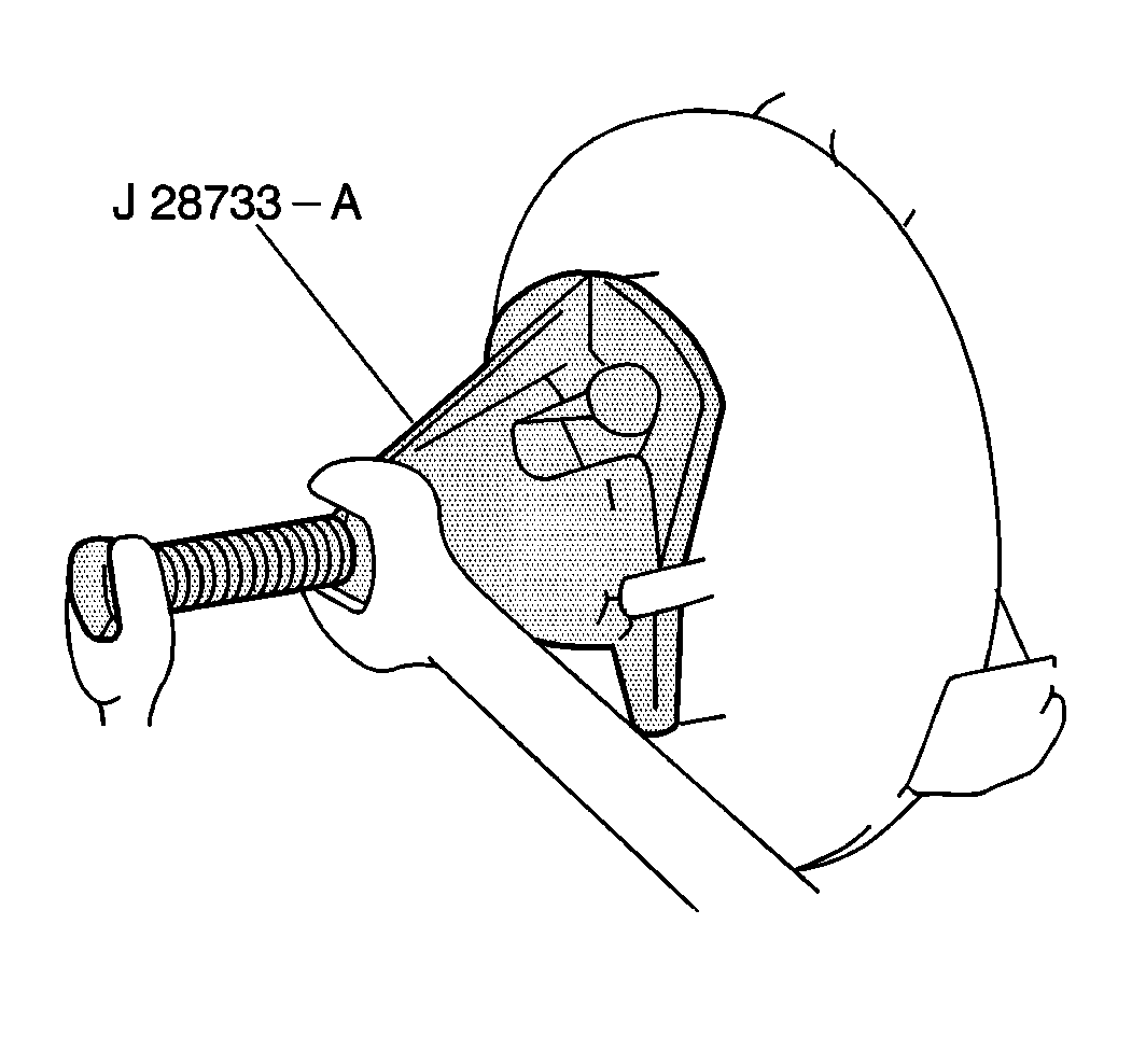
J 28733-B Front Hub Spindle Remover
- Raise and suitably support the vehicle. Refer to Lifting and Jacking the Vehicle in General Information.
- Remove the tire and the wheel. Refer to Tire and Wheel Removal and Installation in Tires and Wheels.
- Loosen the drive axle shaft nut one turn. Refer to Wheel Drive Shaft Replacement in Drive Axle.
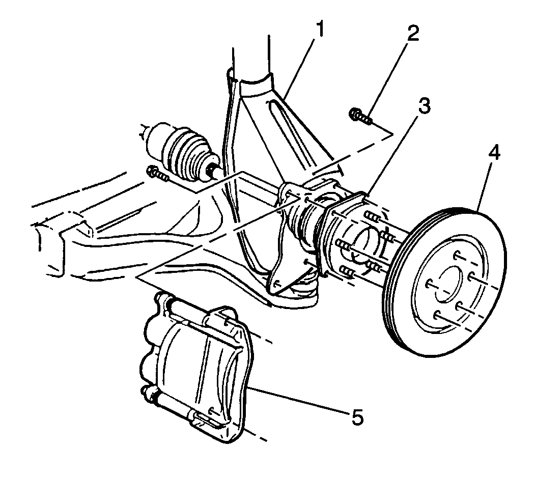
- Remove the caliper and mounting bracket (5). Refer to Brake Caliper Bracket Replacement in Front Disc Brakes.
- Remove the rotor (4). Refer to Front Brake Rotor Replacement in Front Disc Brakes.
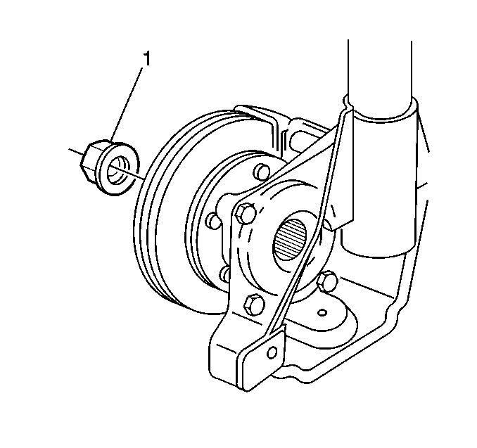
- Remove the drive axle shaft nut (1).
- Loosen the hub/bearing to knuckle/strut attaching bolts.
- Use the J 28733-B in order to push the axle splines back out of the hub/bearing.
- Remove the hub/bearing to knuckle attaching bolts.
- Remove the ABS sensor mounting bolt and position the ABS sensor aside in order to prevent damage.
- Remove the hub/bearing.
- Inspect all components for wear or damage.
Important: Do NOT remove the nut at this time. Failure to follow the proper removal sequence may cause permanent bearing damage.


Important: Protect the axle seals (boots) from damage during handling.
Installation Procedure
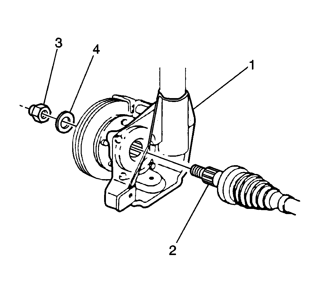
- Install the hub/bearing onto the axle shaft splines.
- Install the knuckle to hub/bearing attaching bolts. Refer to Wheel Drive Shaft Replacement in Drive Axle.
- Properly position the ABS sensor and install the mounting bolt.
- Install the rotor (4). Refer to Front Brake Rotor Replacement in Front Disc Brakes.
- Install the brake caliper and mounting bracket (5). Refer to Brake Caliper Bracket Replacement in Front Disc Brakes.
- Install a new drive axle nut.
- Install the tire and wheel assembly. Refer to Tire and Wheel Removal and Installation in Tires and Wheels.
- Lower the vehicle.


Tighten
Tighten Drive Axle Nut to 215 N·m (159 lb ft)
