Step
| Action
| Value(s)
| Yes
| No
|
1
| Inspect fuse 10 in the fuse block.
Is fuse 10 open?
| --
| Go to
Step
2
| Go to
Step 3
|
2
|
- Replace fuse 10.
- Inspect fuse 10 again.
Is fuse 10 open again?
| --
| Go to
Step
13
| Go to
Step 3
|
3
| Do the following components operate normally?
- Radio hold time/memory presents
- Audible warnings (fasten belt reminder chime and key-in ignition
chime).
| --
| Go to
Step 4
| Go to
Step 14
|
4
| Inspect fuse 12 in the fuse block.
Is fuse 12 open?
| --
| Go to
Step
5
| Go to
Step 6
|
5
|
- Replace fuse 12.
- Turn the ignition switch to the RUN position.
- Inspect fuse 12 again.
Is fuse 12 open again?
| --
| Go to
Step
15
| Go to
Step 6
|
6
|
- Turn the ignition switch to the LOCK position.
- Turn the ignition switch to the RUN position.
- Observe the Service Engine Soon (MIL) indicator lamp in the instrument
cluster.
Does the MIL light?
| --
| Go to
Step
7
| Go to
Step 16
|
7
|
- Turn the ignition switch to the LOCK position.
- Disconnect the theft deterrent module.
- Use a test light to probe between the theft deterrent module harness
connector terminal A1 and the ground.
Does the test light illuminate?
| --
| Go to
Step
8
| Go to
Step 17
|
8
|
- Turn the ignition switch to the RUN position.
- Use a test light to probe between the theft deterrent module harness
connector terminal A2 and the ground.
Does the test light illuminate?
| --
| Go to
Step
9
| Go to
Step 18
|
9
| Use a test light to probe between B+ and the theft deterrent module
harness connector terminal B5.
Does the test light illuminate?
| --
| Go to
Step
10
| Go to
Step 19
|
10
|
- Turn the ignition switch to the LOCK position.
- Connect a fused jumper between the theft deterrent module harness
connector terminal A5 and the ground.
- Turn the ignition switch to the RUN position.
Does the SECURITY indicator light illuminate?
| --
| Go to
Step 21
| Go to
Step 11
|
11
|
- Turn the ignition switch to the LOCK position.
- Remove and disconnect the instrument cluster. Refer to
Instrument Cluster Replacement
in Instrument Panel, Gages and Console for service
procedures.
- Use a DMM to measure the resistance between the instrument cluster
harness connector terminal D16 and the theft deterrent module harness
connector terminal A5.
Is the resistance within the specified range?
| Less than 2 ohms
| Go to
Step 12
| Go to
Step
20
|
12
| The SECURITY indicator is inoperative due to a problem
with the instrument cluster. Refer to
Instrument Cluster System Check
in Instrument Panel, Gages and Console for more information. Make repairs
as needed.
Has the repair been made?
| --
| Go to
Step
22
| --
|
13
| Repair the short to ground in CKT 640.
Has the repair been made?
| --
| Go to
Step
22
| --
|
14
| Inspect for the following conditions:
| • | A poor connection or an open in the power feed CKT to fuse 10.
Refer to
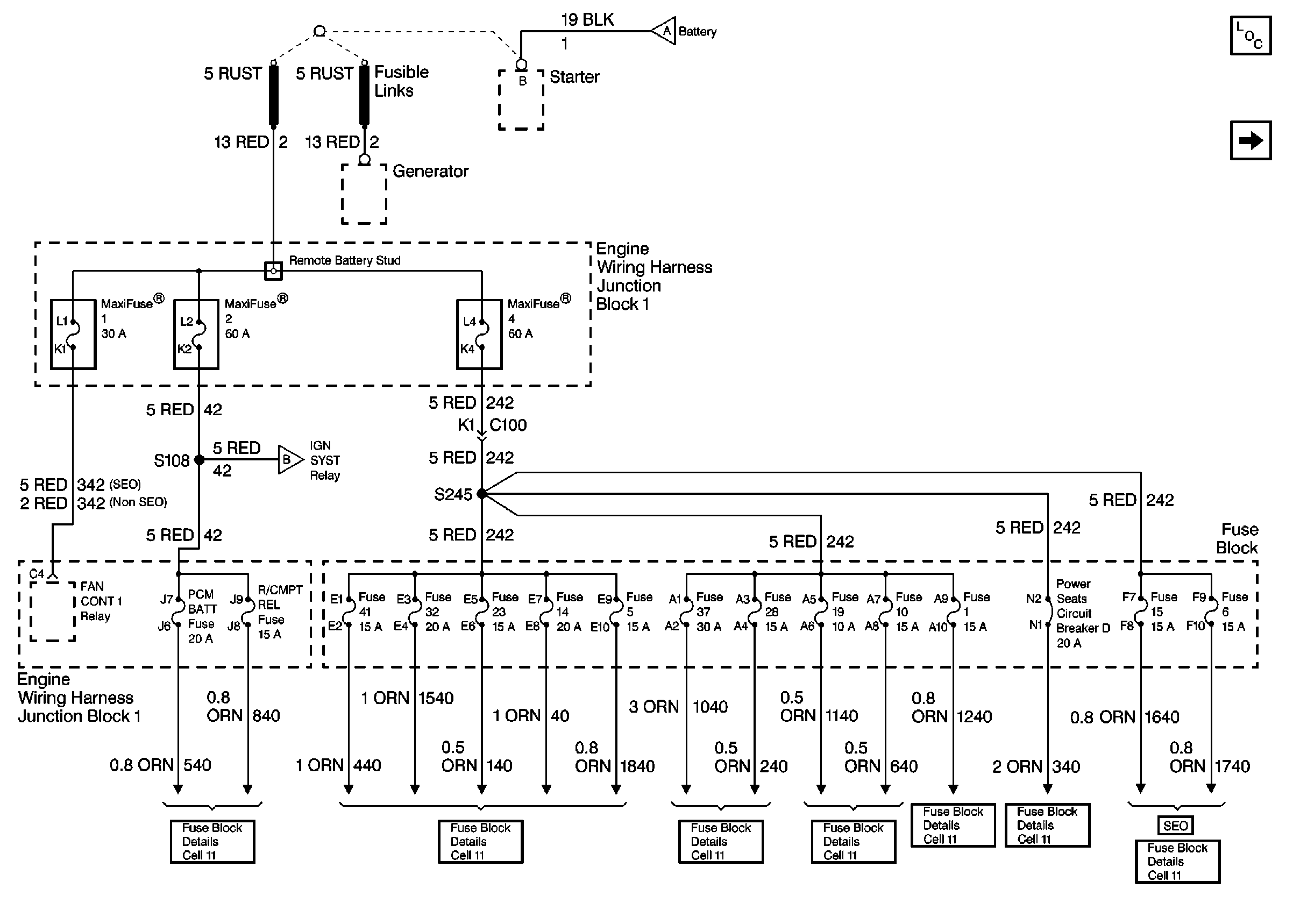
Cell 10: Generator, Starter, Fusible Links, MaxiFuse® 1, 2 and
4

in Wiring Systems
for schematic. |
| • | Inspect G201 for a clean, tight connection. |
Has the repair been made?
| --
| Go to
Step
22
| --
|
15
| Repair a short to ground in CKT 339. Refer to
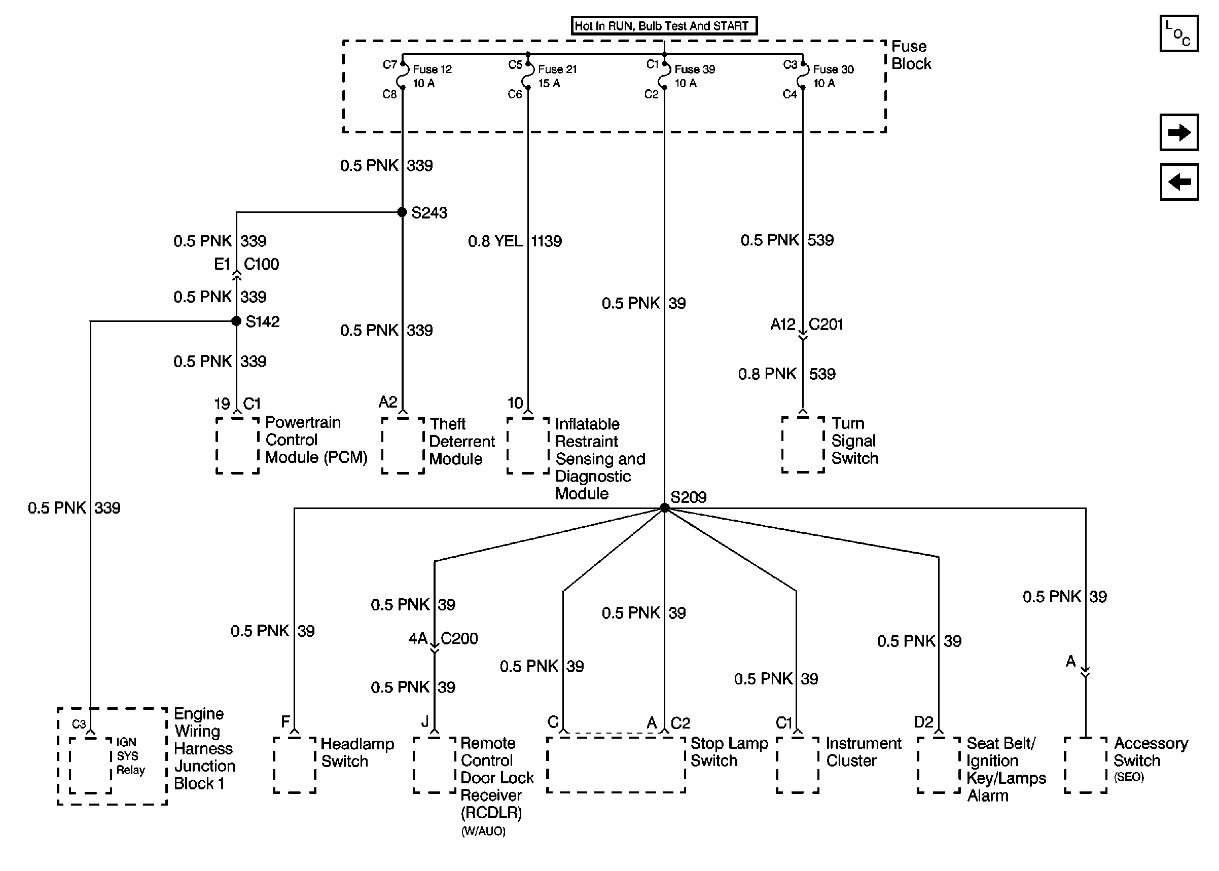
Cell 11: Anti-Theft PCM (12), Air Bag (21), Turn Signal (30), and IP
Electronics Ignition Feed (39) Fuses

in Wiring Systems for schematic.
Has the repair been made?
| --
| Go to
Step
22
| --
|
16
|
- Inspect for a poor connection or an open in the power feed CKT
to fuse 12. Refer to
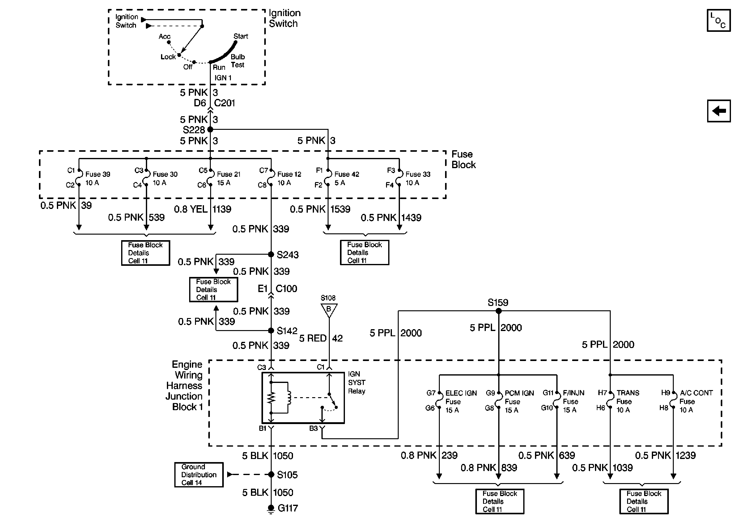
Cell 10: Fuses 12, 21, 30, 33, 39, and 42

in Wiring Systems for schematic.
- Make repairs as needed.
Has the repair been made?
| --
| Go to
Step
22
| --
|
17
| Repair a poor connection or an open in CKT 640.
Has the repair been made?
| --
| Go to
Step
22
| --
|
18
| Repair a poor connection or an open in CKT 339. Refer to
Cell 11: Anti-Theft PCM (12), Air Bag (21), Turn Signal (30), and IP
Electronics Ignition Feed (39) Fuses

in Wiring Systems for schematic.
Has the repair been made?
| --
| Go to
Step
22
| --
|
19
|
- Repair a poor connection or an open in CKT 1550.
- Inspect for a clean tight G201.
Has the repair been made?
| --
| Go to
Step
22
| --
|
20
| Repair a poor connection or an open in CKT 728.
Has the repair been made?
| --
| Go to
Step
22
| --
|
21
|
- Inspect the theft deterrent module harness connector for poor
terminal contact.
- If the connector is OK, replace the theft deterrent module. Refer
to
Theft Deterrent Module Replacement
for replacement procedures.
Has the repair been made?
| --
| Go to
Step
22
| --
|
22
|
- Turn the ignition switch to the LOCK position.
- Reconnect any connectors/components removed.
Is the action complete?
| --
| Go to
Vehicle Theft Deterrent (VTD) System Check
| --
|


