For 1990-2009 cars only
Removal Procedure
Tools Required
J 35917 Tie Rod Puller/Ball Joint Remover
- Raise and suitably support the vehicle. Refer to Lifting and Jacking the Vehicle in General Information.
- Remove the tire and wheel assembly. Refer to Tire and Wheel Removal and Installation in Tires and Wheels.
- Remove the stabilizer shaft to lower control arm insulator clamp bolts.
- Remove the lower ball joint cotter pin and nut.
- Use the J 35917 to separate the ball joint from the lower control arm.
- Scribe bolt location for alignment.
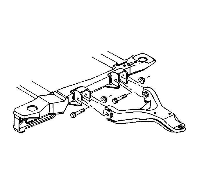
- Remove the lower control arm.

Remove the lower control arm-to-frame attaching nuts and bolts.
Installation Procedure
- Install the lower control arm.
- Install the lower control arm bolts from the front of the frame.
- Pivot the lower control arm up to the ball joint.
- Install the ball joint and the ball joint stud nut to the lower control arm. Tighten the ball joint nut in order to align the next slot in the nut with the cotter pin hole in the stud.
- Install a new cotter pin.
- Install the stabilizer shaft to the lower control arm insulator clamp.
- Install the tire and wheel assembly. Refer to Tire and Wheel Removal and Installation in Tires and Wheels.
- Lower the vehicle.

Important:
• Tighten in order to align the next slot in the ball joint nut
with the cotter pin hole in the ball joint stud. • DO NOT tighten the ball joint nut more than 60 degrees
(1 flat) to align with the cotter pin hole. • DO NOT loosen the nut at any time during the installation.
Tighten
| • | Tighten the lower control arm-to-frame nuts to 70 N·m (52 lb ft). |
| • | Tighten the lower ball joint nut to 85 N·m (63 lb ft). |
Tighten
Tighten the stabilizer shaft bushing clamp bolts to 48 N·m
(35 lb ft).
