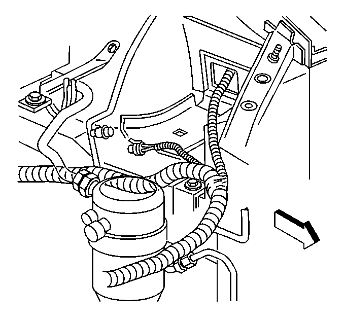
The A/C electrical system consists of the following components:
A/C System Components
| • | The body control module (BCM) |
| • | The A/C refrigerant pressure sensor |
| • | The A/C compressor clutch |
| • | The A/C compressor clutch relay |
| • | The A/C request signal (CJ3, C60) through the Class II
serial data circuit |
| • | The powertrain control module (PCM) |
A/C Request Signal
The A/C control assembly provides a 12 volt A/C request signal
to the body control module (BCM). The BCM then transmits the request through
the Class II serial data circuit to the PCM). The PCM uses this information
to adjust the idle speed before turning on the A/C clutch. If this signal
is not available to the PCM, the A/C compressor will be inoperative. Refer
to
Powertrain Control Module Controlled Air Conditioning (A/C) Circuit Diagnosis
for A/C clutch wiring diagrams and diagnosis of the A/C clutch electrical
system. When diagnosing the A/C controller and refrigerant portion of the
HVAC system, use the
Cooling Insufficient - Air Conditioning (A/C) System
diagnosis in HVAC Systems-Manual.
A/C Refrigerant Pressure Sensor

The A/C refrigerant pressure
sensor signal indicates high side refrigerant pressure to the PCM. The PCM
uses this information to adjust the idle air control valve to compensate
for the higher engine loads present with high A/C refrigerant pressures
and to control the cooling fans. A fault in the A/C refrigerant pressure
sensor signal will cause
DTC P0530 Air Conditioning (A/C) Refrigerant Pressure Sensor Circuit
to set.
When A/C is selected the PCM increases the engine idle
speed just prior to A/C clutch engagement for better idle
quality. In addition the PCM will command the cooling fans
on during A/C operation. The PCM monitors the A/C refrigerant
pressure. If the A/C refrigerant pressure, and engine
operating conditions are within a specific calibrated
acceptable ranges the PCM will enable the A/C compressor
relay. This is accomplished by providing a ground path
for the A/C relay coil within the PCM. When the A/C compressor
relay is enabled battery voltage is supplied to the compressor
clutch coil.
The PCM will enable the A/C compressor clutch whenever the engine is
running and the A/C has been requested, unless any of the following conditions
are met:
| • | The throttle angle is more than 90 percent. |
| • | The A/C head pressure is more than 427 psi (4.27 volts)
or less than 41 psi (0.35 volt) as determined by the A/C refrigerant
pressure sensor. |
| • | The ignition voltage is less than 9.5 volts. |
| • | The engine speed is more than 6900 RPM for 5 seconds. |
| • | The engine coolant temperature (ECT) is more than 121°C (250°F). |
| • | The intake air temperature (IAT) is less than 0°C (32°F) |
For more information regarding the A/C system, refer to
HVAC Compressor Controls Circuit Description
in HVAC Systems -
Manual.

