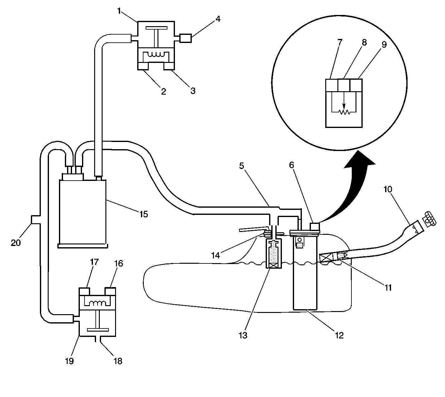
Refer to Engine Controls Schematic
EVAP Control System Overview

System Description
The EVAP canister purge valve allows manifold vacuum to purge the canister. The powertrain control module (PCM) supplies a Ground to energize the purge valve (purge ON). The EVAP purge valve control is pulse width modulated (PWM) or Turned ON and OFF several times a second. The duty cycle (pulse width) is determined by engine operating conditions including load, throttle position, coolant temperature and ambient temperature. The duty cycle is calculated by the PCM and the output is commanded when the appropriate conditions have been met.
The EVAP Vent valve is used to seal the EVAP system during diagnostic tests. The fuel tank pressure sensor is used to monitor vacuum in the system during the diagnostic tests.
A stuck closed EVAP canister purge valve, stuck open EVAP vent valve, disconnected or damaged EVAP Purge line or vent hose, leaking fuel cap, or fill neck should set a DTC P0440. A small leak in the EVAP system should set a DTC P0442. An EVAP vent valve stuck closed, a restricted vent hose, or a blocked EVAP canister should set a DTC P0446. A continuous purge condition with no purge commanded by the PCM (EVAP purge valve stuck open or leaking) should set a DTC P1441. Refer to the DTC tables for further diagnostic procedures regarding the EVAP system.
The EVAP system includes the following components:
| • | The EVAP canister |
| • | The EVAP canister purge valve |
| • | The EVAP vent valve |
| • | The EVAP vapor pipes |
| • | The EVAP purge pipes |
| • | The EVAP fresh air vent hose |
| • | The fuel tank |
| • | The fuel pipes and hoses |
| • | The fuel fill cap |
| • | The fuel fill pipe |
Diagnostic Aids
Check for the following conditions:
| • | Cracked or punctured EVAP canister |
| • | Damaged or disconnected source vacuum line, EVAP purge line, vent hose or fuel tank vapor line |
| • | Poor connection at the PCM |
| • | Inspect harness connectors for the following conditions: |
| - | Backed out terminals |
| - | Improper mating |
| - | Broken locks |
| - | Improperly formed or damaged terminals |
| - | Poor terminal to wire connection |
| • | Damaged harness -- Inspect the wiring harness to the EVAP vent valve, the EVAP purge valve, and the fuel tank pressure sensor for an intermittent open or short circuit. |
| • | Kinked, pinched or plugged vacuum source, EVAP purge, or fuel tank vapor line. Verify that the lines are not restricted. |
| • | Carbon being released into the system. |
Step | Action | Values | Yes | No | ||||||||||
|---|---|---|---|---|---|---|---|---|---|---|---|---|---|---|
1 | Did you perform the Powertrain On-Board Diagnostic (OBD) System Check? | -- | ||||||||||||
2 | Did any other DTC set? | -- | Go to applicable DTC | |||||||||||
3 | Inspect the EVAP system for the following conditions:
Did you find and correct the condition? | -- | ||||||||||||
4 |
Does the scan tool indicate fuel tank pressure near the specified value? | 0 in H2O | Go to DTC P0453 Fuel Tank Pressure Sensor Circuit High Voltage | |||||||||||
5 |
Important: DO NOT exceed the pressure in the specified value. Did you achieve the specified value? | 1.25 kPa (5 in H2O) | ||||||||||||
6 | Use the EVAP service station to maintain fuel tank pressure at the specified value. Does the scan tool indicate fuel tank pressure at the specified value? | 1.25 kPa (5 in H2O) | Go to DTC P0452 Fuel Tank Pressure Sensor Circuit Low Voltage | |||||||||||
7 | With a scan tool, command the vent valve OFF. Does the pressure decrease to near the specified value within 2 minutes with the rotary switch in the Off/Hold position? | 0 kPa (0 in H2O) | Go to DTC P0446 Evaporative Emission (EVAP) Vent System Performance | |||||||||||
8 |
Does the scan tool indicate a fuel tank pressure decrease to the specified lower value within 15 Seconds? | 1.25 kPa (5 in H2O) 0 kPa (0 in H2O) | Go to DTC P1441 Evaporative Emission (EVAP) System Flow During Non-Purge | |||||||||||
9 |
Important:: Do not exceed the pressure in the specified value. Does the EVAP pressure decrease to less than the second specified value within 2 minutes? | 15 in H2O 10 in H2O | Go to DTC P0442 Evaporative Emission (EVAP) System Small Leak Detected | System OK |
