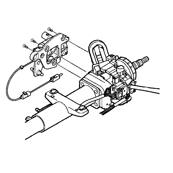
Removal Procedure
- Remove the shift lever assembly. Refer to
Shift Lever Replacement
.
- Remove the knee bolster. Refer to
Driver Knee Bolster Bracket Replacement
or
Passenger Knee Bolster Bracket Replacement
in Instrument Panel,
Gages, and Console.
- Disconnect the electrical connector from the A/T shift lock control
actuator.
- Remove the lock control actuator. Refer to
Automatic Transmission Shift Lock Actuator Replacement
in Shift
Lock Control.

- Place the lock cylinder
in the OFF-LOCK position.
- Disconnect the linear shift assembly cable from the ignition switch.
- Remove the screws from the linear shift assembly.
- Remove the linear shift assembly from the steering column.
Installation Procedure

Notice: Use the correct fastener in the correct location. Replacement fasteners
must be the correct part number for that application. Fasteners requiring
replacement or fasteners requiring the use of thread locking compound or sealant
are identified in the service procedure. Do not use paints, lubricants, or
corrosion inhibitors on fasteners or fastener joint surfaces unless specified.
These coatings affect fastener torque and joint clamping force and may damage
the fastener. Use the correct tightening sequence and specifications when
installing fasteners in order to avoid damage to parts and systems.
- Install the linear shift assembly to the steering column.
Tighten
Tighten the shift assembly screws to 3.5 N·m (31 lb in).
- Connect the electrical connector to the automatic transmission
shift lock control actuator.
- Install the linear shift assembly cable onto the ignition switch.
- Install the lock control actuator. Refer to
Automatic Transmission Shift Lock Actuator Replacement
in Shift
Lock Control.
- Install the shift lever assembly. Refer to
Shift Lever Replacement
.
- Verify the replacement by performing the following test:
| 6.1. | Inspect the cable routing for clearance with the brake switches. |
| 6.2. | Move the shift lever from PARK to REVERSE and back to the PARK
position and turn the ignition key to the OFF position. |
| 6.3. | Verify that the shift lever cannot be removed from PARK when the
ignition key is in the OFF position. |
| 6.4. | Turn the ignition key to the ON position and verify that the shift
lever can be removed from PARK. |
| 6.5. | Return the shift lever to the PARK position and verify that the
ignition key can be turned to the OFF position and removed without difficulty.
If you can remove the key easily, you have completed the verification. If
the key cannot be removed or requires high effort, continue with the verification
test. |
| 6.6. | Adjust the cable length by moving the white adjustment tab outwards
from the adjuster body located in the middle of the cable. |
| 6.7. | Move the shift lever from PARK to reverse and back to the PARK
position and turn the ignition key to the OFF position. |
| 6.8. | Press the white adjustment tab inwards until it locks in place.
Verify proper operation by repeating the test. |
- Install the knee bolster. Refer to
Driver Knee Bolster Bracket Replacement
or
Passenger Knee Bolster Bracket Replacement
in Instrument Panel,
Gages, and Console.


