Steering Wheel Inflatable Restraint Module Replacement Impala
Tools Required
J 44298 Driver Air Bag Removal Tool
Removal Procedure
Caution: A deployed dual stage inflator module will look the same whether one or both stages were used. Always assume a deployed dual stage inflator module has an active stage 2. Improper handling or servicing can activate the inflator module and cause personal injury.
Caution: Refer to SIR Caution in the Preface section.
Caution: Refer to SIR Inflator Module Handling and Storage Caution in the Preface section.
- Disable the SIR system. Refer to SIR Disabling and Enabling .
- If equipped with steering column tilt, adjust the steering wheel to the lowest position.
- The back side of steering wheel has 4 openings for access to the driver supplemental inflatable restraint (SIR) module retainers. Turn the steering wheel until 2 of the openings are accessible, straight above the steering column.
- Adjust and install the J 44298 into the top 2 openings.
- Push the handle towards the instrument panel to release both module mounting posts from the retainer.
- Repeat this procedure for the remaining openings.
- Pull the module gently away from the steering wheel.
- Remove the connector position assurance (CPA) for each module electrical connector.
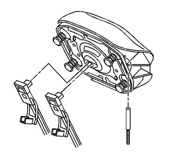
- Disconnect the yellow SIR coil lead wire connectors from the module.
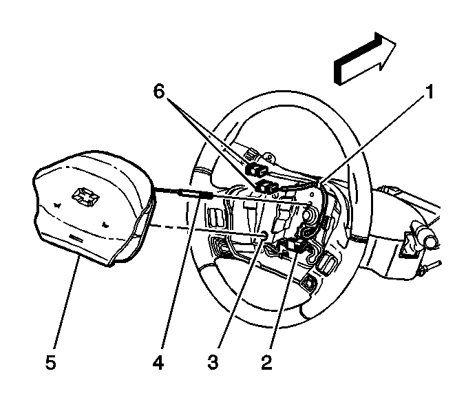
- Rotate the horn wire (4) counterclockwise until the wire unlocks from the cam tower post. Remove the horn wire from the steering wheel.
- Remove the driver SIR module (5).
- Fully deploy the module before disposal. If the module was replaced under warranty, fully deploy and dispose of the module after the required retention period. Refer to Inflator Module Handling and Scrapping .
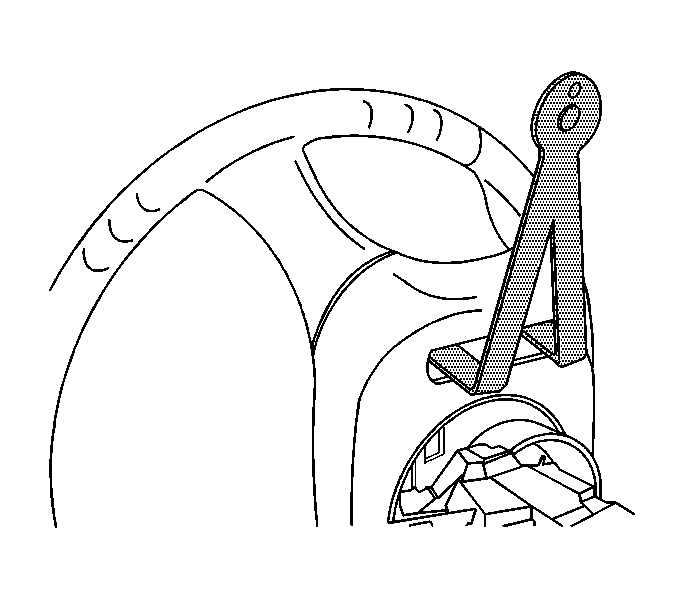
Important: The driver air bag removal tool must be seated correctly to function.
Installation Procedure
- Position the horn wire (4) into the cam tower post. Rotate the horn wire clockwise until locked. The horn wire must be below the top, left, module mounting post.
- Connect the yellow SIR coil lead wires to the module connectors. Connect pink to pink and gray to gray.
- Install the CPA to each connector.
- Make sure the wires are routed and secured correctly:
- Install the 4 mounting posts on the module to the 4 holes in the steering wheel:
- Enable the SIR system. Refer to SIR Disabling and Enabling .


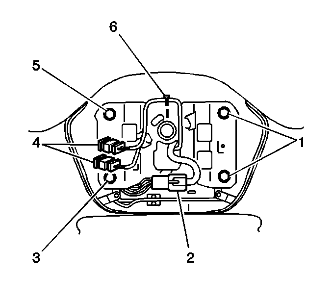
| • | Secure the black redundant controls connector (2) to the feature at the 6 o'clock position on the steering wheel shroud. For the base steering wheel, the feature is at the 5 o'clock position. |
| • | Route the yellow SIR coil lead wires counterclockwise away from the 4 module mounting holes (1,3,5) and away from the center steering wheel nut. Insert the wire bundle into the retainer (6). |
Important: Do not force the module into place.
| • | Set the left and right sides of the module evenly to the steering wheel. |
| • | Press evenly on both sides until a clicking sound is heard. |
Steering Wheel Inflatable Restraint Module Replacement Monte Carlo
Removal Procedure
- Disable the SIR system. Refer to SIR Disabling and Enabling .
- If equipped with steering column tilt, adjust the steering wheel to the lowest position.
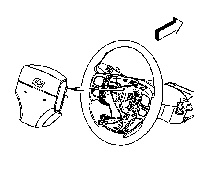
- The back side of the steering wheel has 3 openings for access to the driver supplemental inflatable restraint (SIR) module retainers. Turn the steering wheel until one of the openings is accessible straight above the steering column.
- Insert a flat-bladed tool into the opening. Twist the tool to release the module mounting post from the retainer.
- Repeat the last two steps for the remaining openings.
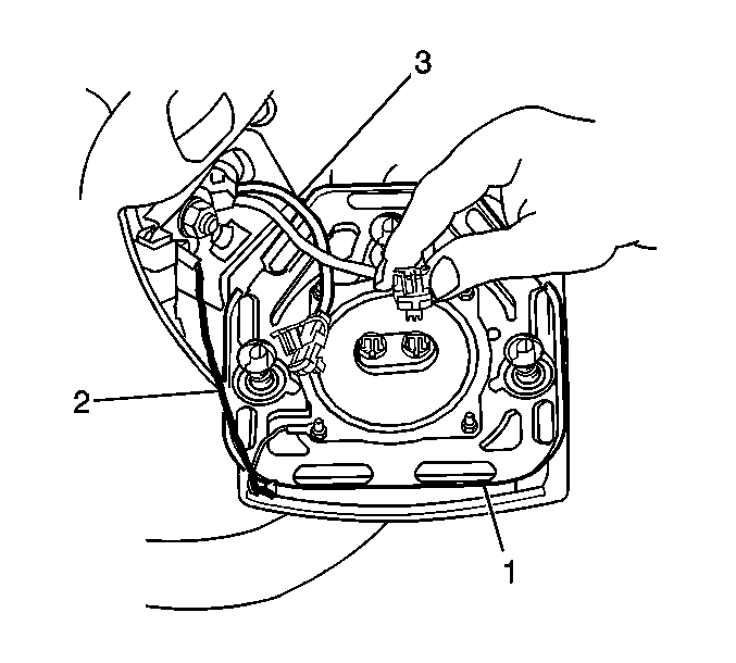
- Pull the module (1) gently away from the steering wheel.
- Remove the connector position assurance (CPA) from each module electrical connector.
- Disconnect the yellow SIR coil lead wire connectors from the module.
- Rotate the horn wire counterclockwise until the wire unlocks from the cam tower post. Remove the horn wire from the steering wheel.
- Remove the driver SIR module.
- Fully deploy the module before disposal. If the module was replaced under warranty, fully deploy and dispose of the module after the required retention period. Refer to Inflator Module Handling and Scrapping .
Caution: Refer to SIR Caution in the Preface section.
Caution: Refer to SIR Inflator Module Handling and Storage Caution in the Preface section.
Caution: A deployed dual stage inflator module will look the same whether one or both stages were used. Always assume a deployed dual stage inflator module has an active stage 2. Improper handling or servicing can activate the inflator module and cause personal injury.
Installation Procedure
- Position the horn wire into the cam tower post. Rotate the horn wire clockwise until locked.
- Connect the yellow SIR coil lead wires to the module connectors. Connect pink to pink and gray to gray.
- Install the CPA to each connector.
- Route and secure the wires correctly:
- Install the 3 mounting posts on the module into the 3 holes (2,4,6) in the steering wheel:
- Enable the SIR system. Refer to SIR Disabling and Enabling .


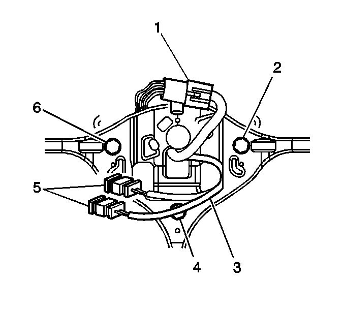
| • | Secure the black redundant controls connector (1) to the feature at the 12 o'clock position on the steering wheel shroud. For the base steering wheel, the feature is at the 2 o'clock position. |
| • | Route the yellow SIR coil lead wires (3) away from the 3 module mounting holes into the correct opening in the steering wheel insert. |
Important: Do not force the module into place.
| • | Set the left and right sides of the module evenly to the steering wheel. |
| • | Gently press evenly on both sides and the bottom of the module until a clicking sound is heard. |
