Removal Procedure
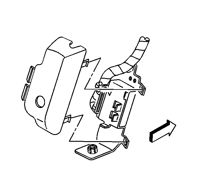
Important: The vehicle communication interface module (VCIM) has a specific set of unique numbers that tie the module to each vehicle. These numbers, the 10-digit station identification (STID) and the 11-digit electronic
serial number (ESN), are used by the National Cellular Network and OnStar® to identify the specific vehicle. Because these numbers are tied to the vehicle identification number of the vehicle, you must never exchange these parts with those of another vehicle.
- Open the rear compartment.
- Remove the black plastic OnStar® cover.
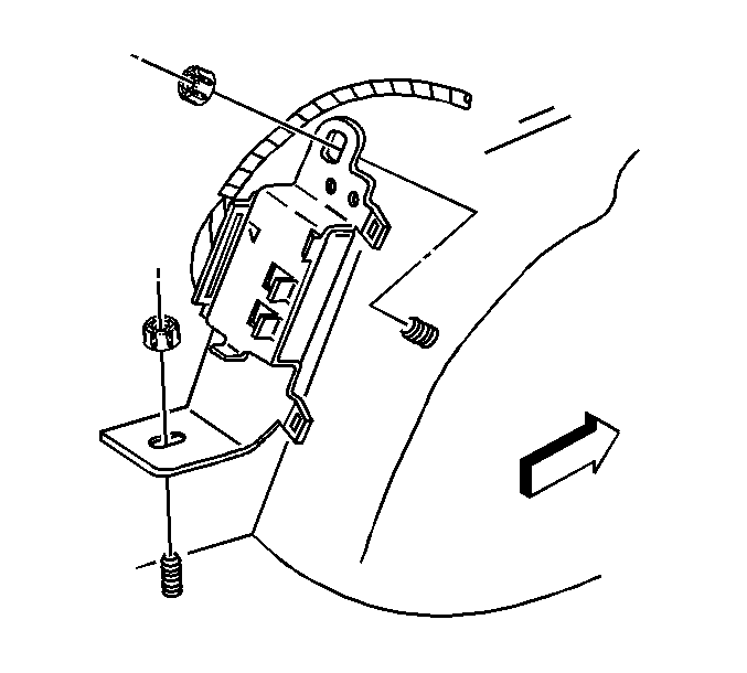
- Remove the communication interface
module bracket nuts.
- Adjust the assembly for access.
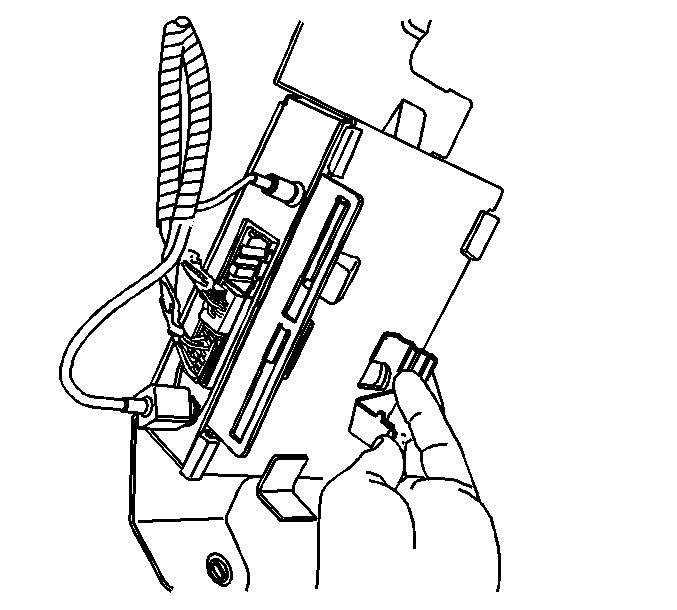
- Disconnect the cellular antenna cable from the communication
interface module by pulling outward on the square plastic housing.
- Disconnect the 2 lower connectors from the module.
- Disconnect the GPS antenna cable from the module by pulling outward on the circular metal sleeve.
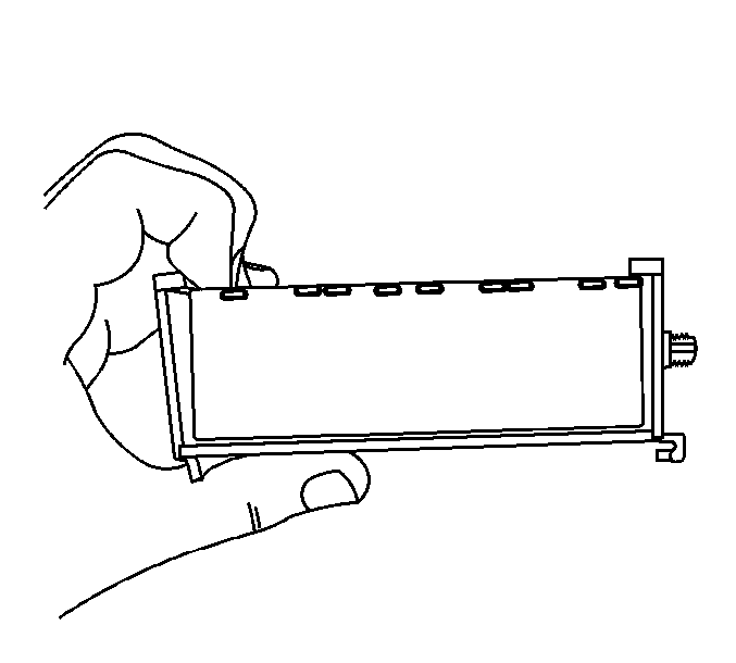
- Perform the following steps:
| 8.1. | Disengage the 2 large, plastic snap features at the inboard edge of the metal bracket, allowing the plastic bracket assembly to drop. |
| 8.2. | Push the plastic bracket assembly slightly outboard. Unhook the outboard plastic tabs. |
| 8.3. | Slide the plastic bracket assembly inboard, under the metal bracket. Remove the plastic bracket assembly from the metal bracket. |
| 8.4. | On bottom side of plastic bracket assembly, directly below the 2 large, plastic snap features, locate the under cut edge. Pull this under cut edge outward, up and over the side of the module. |
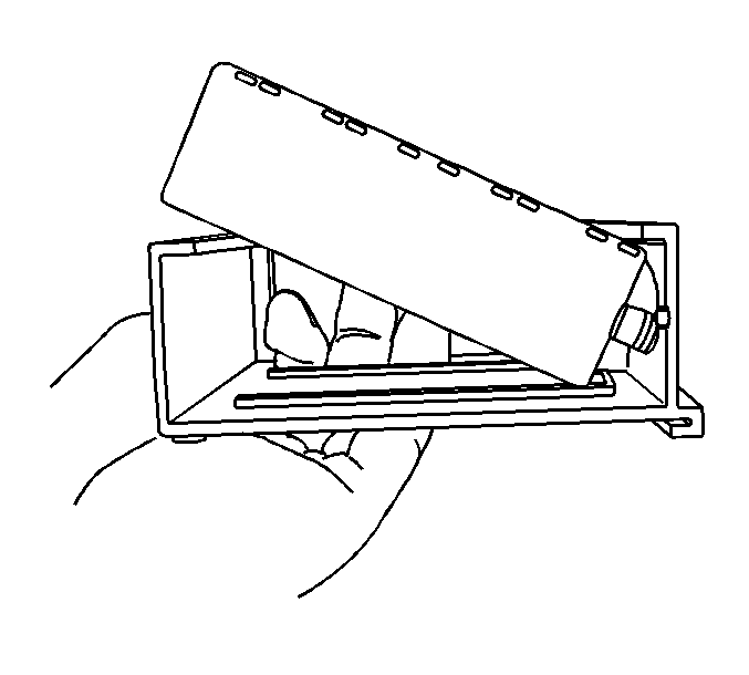
- Note the orientation of the module in the plastic bracket
for installation. Slide the module out of the plastic bracket.
Installation Procedure

- When replacing the CIM, perform the following steps:
| 1.1. | Record the 11-digit ESN and the 10-digit STID number from the label on the new VCIM. |
| 1.2. | Align the connector side of the module to the large cutout on the plastic bracket. Insert the module into the plastic bracket. Make sure the small GPS connector is inserted into the small round hole in the plastic bracket. |

- Perform the following steps:
| 2.1. | Spread the large tang side of the plastic bracket over the edge of the module. The bottom, undercut edge of the plastic bracket will snap over the bottom of the module when fully seated. |
| 2.2. | The connectors on the module must be outboard. Slide the plastic bracket assembly outboard, under the metal bracket. |
| 2.3. | Engage the outboard plastic tabs to the outboard edge of the metal bracket. |
| 2.4. | Squeeze the plastic bracket assembly upward until the large, plastic snap-fingers engage on the inboard edge of the metal bracket. |

- Gently connect the GPS antenna cable to the module by
pushing inward on the circular metal sleeve.
- Connect the 2 lower connectors to the module.
- Connect the cellular antenna cable to the module by pushing inward on the square plastic housing.
Important: After replacing the CIM, you must reconfigure the OnStar® system. Failure to reconfigure the system will result in an additional customer visit for repair.
- Reconfigure the OnStar® system. Refer to
OnStar Reconfiguration
.

- Position the assembly to the studs.
Notice: Refer to Fastener Notice in the Preface section.
- Install the communication interface module bracket nuts.
Tighten
Tighten the nuts to 4 N·m (35 lb in).

- Install the plastic OnStar® cover.
- Close the rear compartment.


