For 1990-2009 cars only
Evaporator Tube Replacement 3.4L
Tools Required
J 39400-A Halogen Leak Detector
Removal Procedure
- Recover the refrigerant. Refer to Refrigerant Recovery and Recharging .
- Remove the air cleaner assembly. Refer to Air Cleaner Assembly Replacement in Engine Controls-3.8L.
- Remove the bolt from the ground wire below the air cleaner assembly.
- Remove the brake pressure modulator valve bracket. Refer to Brake Pressure Modulator Valve Bracket Replacement in Antilock Brake System.
- Disconnect the electrical connector from the brake fluid level sensor.
- Remove the oxygen sensor connector from the fuel injector sight shield rear bracket.
- Remove the master cylinder mounting nuts.
- Remove the master cylinder from the brake booster and position aside.
- Remove the engine vacuum line from the brake booster.
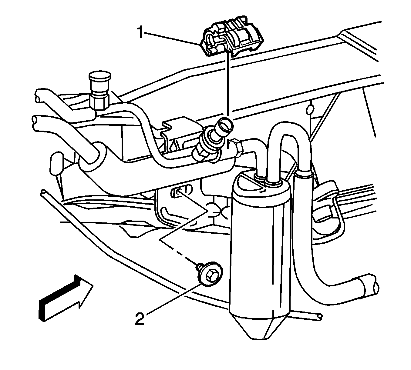
- Remove the A/C line coupling from the evaporator tube to receiver dehydrator tube (1). Refer to Air Conditioning Line/Tube Connector Removal/Replacement .
- Remove the receiver dehydrator mounting bolt (2).
- Disconnect the receiver dehydrator from the evaporator tube.
- Remove the block fitting nut that secures the evaporator tube to the A/C compressor hose assembly.
- Disconnect the evaporator tube from the A/C compressor hose assembly.
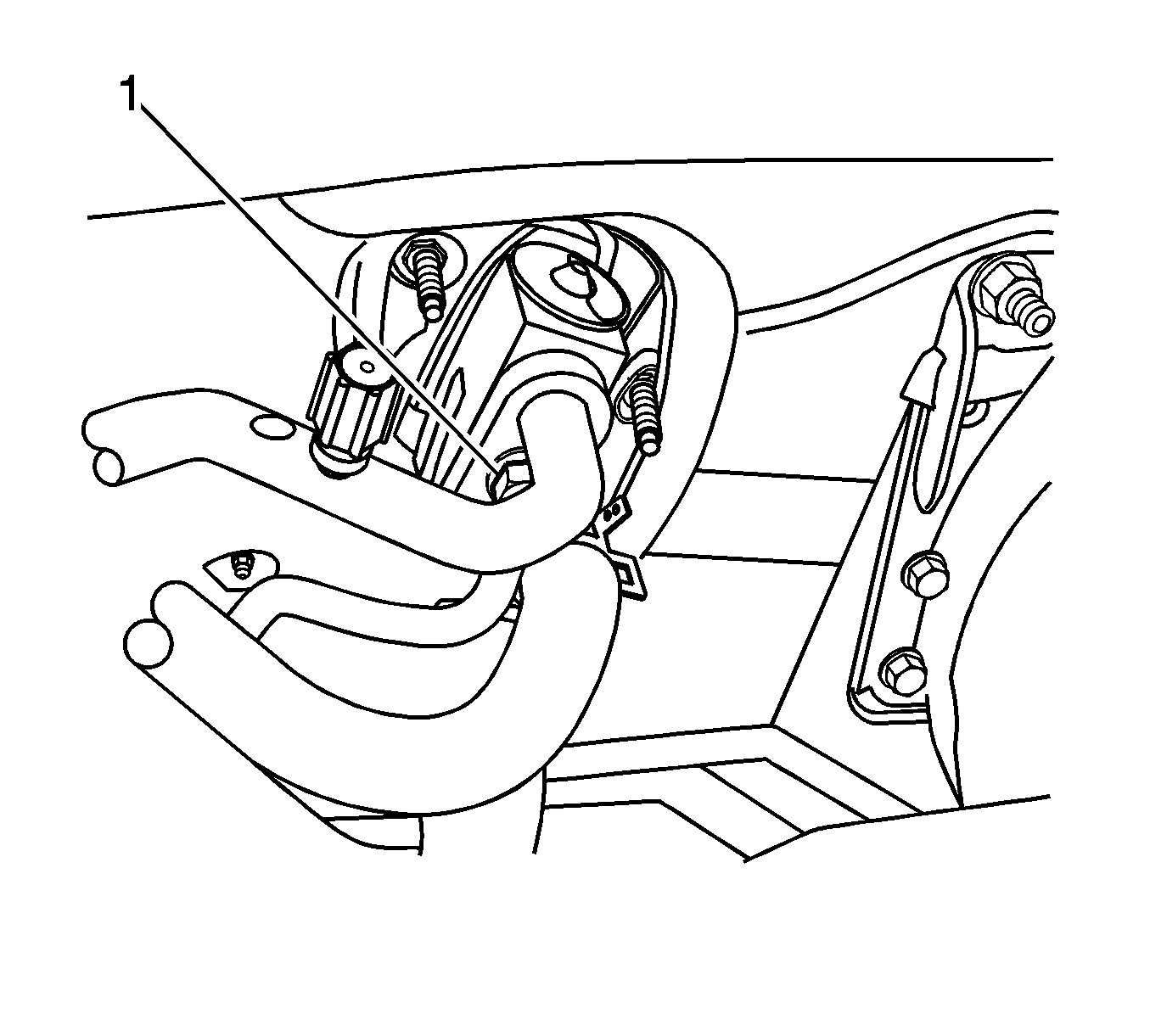
- Remove the block fitting nut (1) that secures the evaporator tube to the TXV.
- Remove the heater hoses from the support bracket and position aside.
- Remove the transmission shift cable from the retainer above the heater hoses and position the cable aside.
- Disconnect the evaporator tube from the TXV.
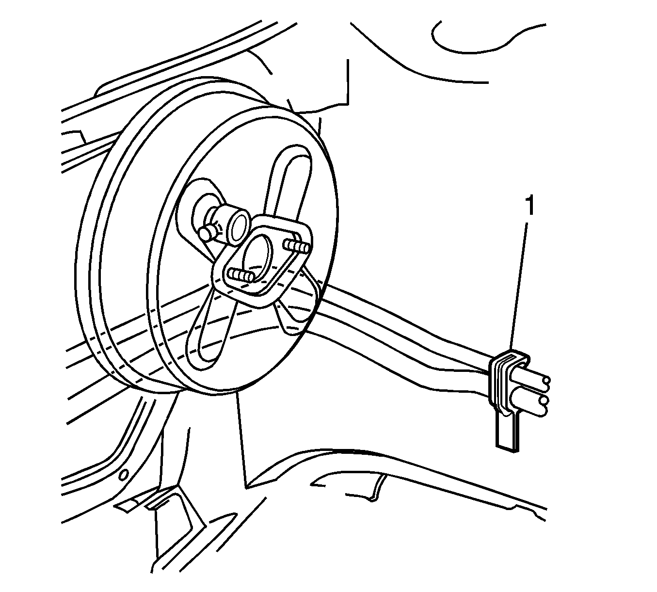
- Remove the evaporator tube from the support clip (1) on the left fender rail .
- Remove the transaxle fluid filler tube. Refer to Transmission Fluid Filler Tube Replacement in Automatic Transaxle - 4T65 - E.
- Disconnect the wire harness electrical connector from the A/C pressure sensor.
- Disconnect the wire harness electrical connector C101 near the top of the left shock tower.
- Remove the evaporator tube from the vehicle.
- Remove the A/C pressure sensor.
- Remove and discard the O-ring seals and seal washers.


Installation Procedure
- Replace the O-ring seal on the receiver dehydrator and A/C pressure sensor. Refer to O-Ring Replacement .
- Install the A/C pressure sensor to the evaporator line.
- Replace the seal washers on the evaporator tube. Refer to Sealing Washer Replacement .
- Install the evaporator tube to the vehicle.
- Install the transaxle fluid filler tube. Refer to Transmission Fluid Filler Tube Replacement in Automatic Transaxle - 4T65 - E.
- Connect the evaporator tube to the support clip (1) on the left fender rail.
- Connect the evaporator tube to the TXV.
- Install the evaporator tube to TXV nut (1).
- Install the oxygen sensor connector to the fuel injector sight shield rear bracket.
- Install the heater hoses to the support bracket.
- Install the transmission shift cable to the retainer above the heater hoses.
- Connect the receiver dehydrator to the evaporator tube.
- Install the A/C line coupling to the evaporator tube and receiver dehydrator tube (1). Refer to Air Conditioning Line/Tube Connector Removal/Replacement .
- Install the receiver dehydrator mounting bolt (2).
- Connect the A/C compressor hose assembly to the evaporator tube.
- Install the A/C compressor hose assembly to evaporator tube block fitting nut.
- Install the brake pressure modulator valve bracket. Refer to Brake Pressure Modulator Valve Bracket Replacement in Antilock Brake System.
- Install the master cylinder to the brake booster.
- Install the nuts to the master cylinder.
- Connect the electrical connector to the brake fluid level sensor.
- Install the engine vacuum line to the brake booster.
- Connect the wire harness electrical connector C101 near the top of the left shock tower.
- Install the bolt to the ground wire below the air cleaner assembly.
- Install the air cleaner assembly. Refer to Air Cleaner Assembly Replacement in Engine Controls-3.8L.
- Evacuate and recharge the A/C system. Refer to Refrigerant Recovery and Recharging .
- Leak test the fittings of the component using J 39400-A .
Notice: Refer to Fastener Notice in the Preface section.
Tighten
Tighten the sensor to 4.7 N·m (41 lb in).


Tighten
Tighten the nut to 17 N·m (13 lb ft).

Tighten
Tighten the bolt to 10 N·m (88 lb in).
Tighten
Tighten the nut to 17 N·m (13 lb ft).
Tighten
Tighten the nuts to 25 N·m (18 lb ft).
Tighten
Tighten the bolt to 10 N·m (89 in lb).
Evaporator Tube Replacement 3.8L
Tools Required
| • | J 39400-A Halogen Leak Detector |
| • | J 38185 Hose Clamp Pliers |
Removal Procedure
- Recover the refrigerant. Refer to Refrigerant Recovery and Recharging .
- Drain the cooling system. Refer to Cooling System Draining and Filling in Engine Cooling.
- Remove the air cleaner assembly. Refer to Air Cleaner Assembly Replacement in Engine Controls - 3.4L.
- Remove the brake pressure modulator valve bracket. Refer to Brake Pressure Modulator Valve Bracket Replacement in Antilock Brake System.
- Disconnect the electrical connector from the brake fluid level sensor.
- Remove the master cylinder mounting nuts.
- Remove the master cylinder from the brake booster and position aside.
- Remove the engine vacuum line from the brake booster.
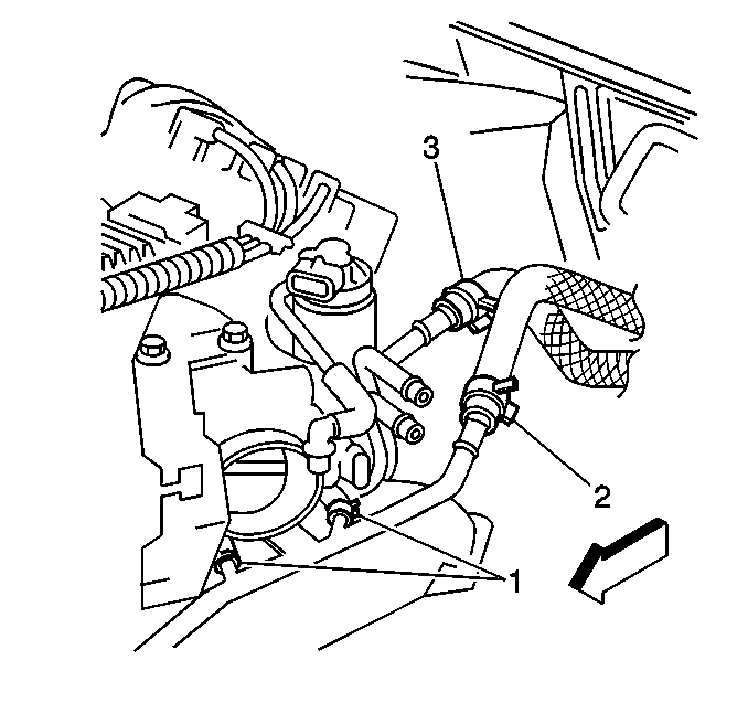
- Use J 38185 in order to position aside the heater hose inlet clamp (3) and outlet clamp (2).
- Disconnect the inlet heater hose (3) and the outlet heater hose (2) from the heater pipes.
- Remove the A/C line coupling from the evaporator tube to receiver dehydrator tube (1). Refer to Air Conditioning Line/Tube Connector Removal/Replacement .
- Remove the receiver dehydrator mounting bolt (2).
- Disconnect the receiver dehydrator from the evaporator tube.
- Remove the block fitting nut that secures the evaporator tube to the A/C compressor hose assembly.
- Disconnect the evaporator tube from the A/C compressor hose assembly.
- Remove the block fitting nut (1) that secures the evaporator tube to the TXV.
- Remove the transmission shift cable from the retainer above the heater hoses and position the cable aside.
- Disconnect the evaporator tube from the TXV.
- Remove the evaporator tube from the support clip (1) on the left fender rail .
- Remove the transaxle fluid filler tube. Refer to Transmission Fluid Filler Tube Replacement in Automatic Transaxle - 4T65-E.
- Disconnect the wire harness electrical connector from the A/C pressure sensor.
- Disconnect the wire harness electrical connector C101 near the top of the left shock tower.
- Remove the evaporator tube from the vehicle.
- Remove the A/C pressure sensor.
- Remove and discard the O-ring seals and seal washers.


Installation Procedure
- Replace the O-ring seal on the receiver dehydrator and A/C pressure sensor. Refer to O-Ring Replacement .
- Install the A/C pressure sensor to the evaporator line.
- Replace the seal washers on the evaporator tube. Refer to Sealing Washer Replacement .
- Install the evaporator tube to the vehicle.
- Install the transaxle fluid filler tube. Refer to Transmission Fluid Filler Tube Replacement in Automatic Transaxle - 4T65-E.
- Connect the evaporator tube to the support clip (1) on the left fender rail.
- Connect the evaporator tube to the TXV.
- Install the evaporator tube to TXV nut (1).
- Install the transmission shift cable to the retainer above the heater hoses.
- Connect the receiver dehydrator to the evaporator tube.
- Install the A/C line coupling to the evaporator tube and receiver dehydrator tube (1). Refer to Air Conditioning Line/Tube Connector Removal/Replacement .
- Install the receiver dehydrator mounting bolt (2).
- Connect the A/C compressor hose assembly to the evaporator tube.
- Install the A/C compressor hose assembly to evaporator tube block fitting nut.
- Install the brake pressure modulator valve bracket. Refer to Brake Pressure Modulator Valve Bracket Replacement in Antilock Brake System.
- Install the master cylinder to the brake booster.
- Install the nuts to the master cylinder.
- Connect the inlet heater hose (3) and the outlet heater hose (2) to the heater pipes.
- Use J 38185 in order to position the heater hose inlet clamp (3) and outlet clamp (2).
- Connect the electrical connector to the brake fluid level sensor.
- Install the engine vacuum line to the brake booster.
- Connect the wire harness electrical connector C101 near the top of the left shock tower.
- Install the air cleaner assembly. Refer to Air Cleaner Assembly Replacement in Engine Controls - 3.4L.
- Evacuate and recharge the A/C system. Refer to Refrigerant Recovery and Recharging .
- Refill the cooling system. Refer to Cooling System Draining and Filling in Engine Cooling.
- Leak test the fittings of the component using J 39400-A .
Notice: Refer to Fastener Notice in the Preface section.
Tighten
Tighten the sensor to 4.7 N·m (41 lb in).


Tighten
Tighten the nut to 17 N·m (13 lb ft).

Tighten
Tighten the bolt to 10 N·m (88 lb in).
Tighten
Tighten the nut to 17 N·m (13 lb ft).
Tighten
Tighten the nuts to 25 N·m (18 lb ft).

