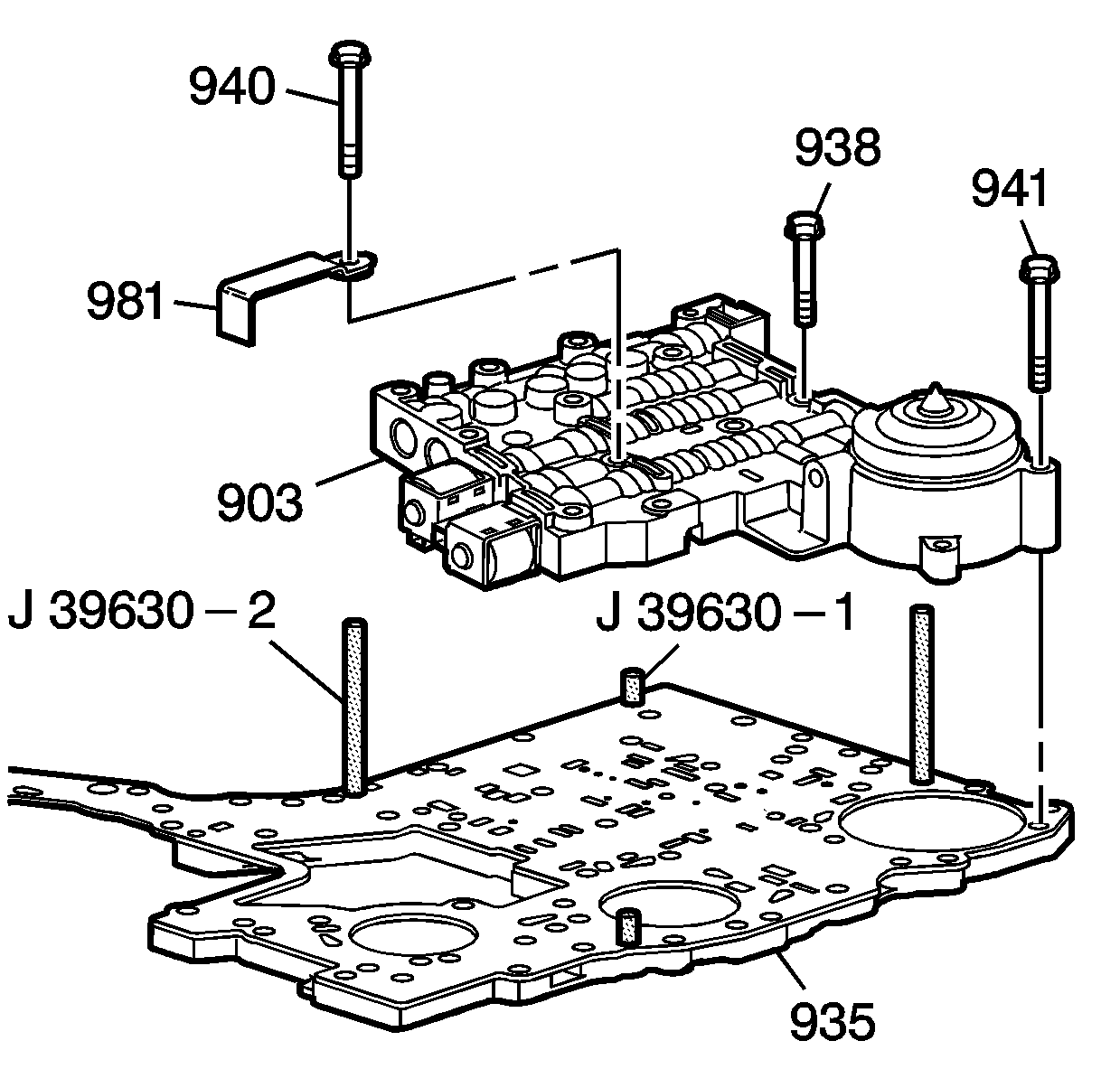
- Install the lower control valve body (903) over the
J 39630-2
.
Notice: Use the correct fastener in the correct location. Replacement fasteners
must be the correct part number for that application. Fasteners requiring
replacement or fasteners requiring the use of thread locking compound or sealant
are identified in the service procedure. Do not use paints, lubricants, or
corrosion inhibitors on fasteners or fastener joint surfaces unless specified.
These coatings affect fastener torque and joint clamping force and may damage
the fastener. Use the correct tightening sequence and specifications when
installing fasteners in order to avoid damage to parts and systems.
- Position the solenoid valve fluid filter retainer (981) onto the lower control valve body (903) and install some of the valve body bolts (938, 940, 941) and hand tighten them.
- Remove the
J 39630-2
.
Tighten
Tighten the bolts (938, 940, 941) in a star pattern to 8-14 N·m (6-10 lb ft).

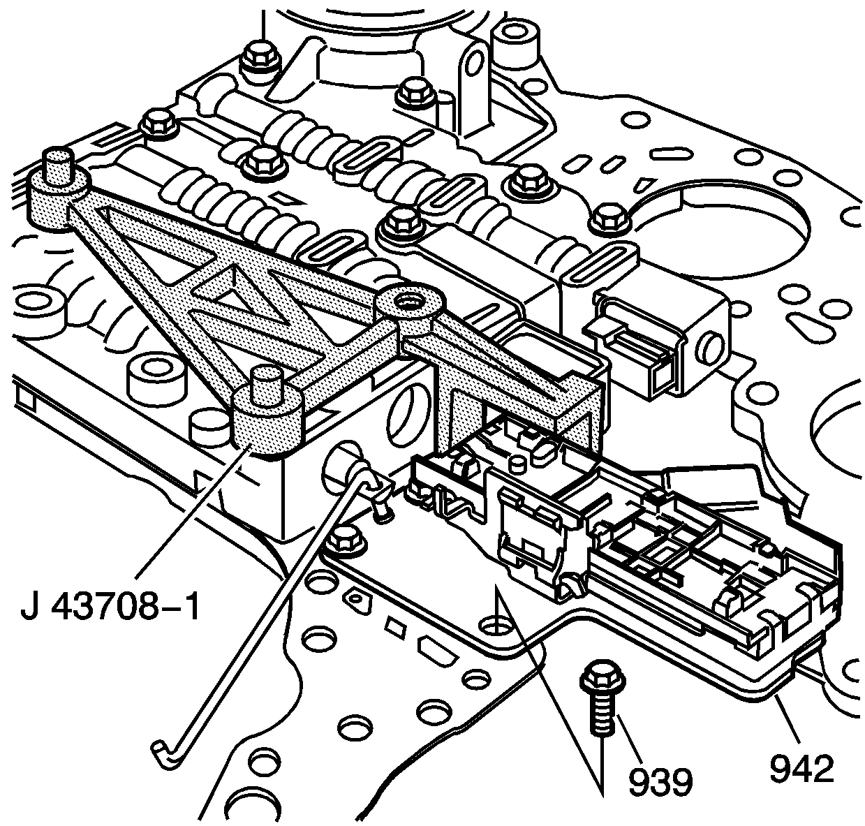
- Position the
J 43708-1
or
DT-47707-R1
onto the lower control valve body, next to the 2-3 shift solenoid valve, and install the two
J 39630-1
.
Important:
- In some cases when replacing the Internal Mode Switch (IMS) it may be necessary to use
DT-47707-R1
Alignment Tool instead of
J 43708-1
.
- Hold the IMS (942) against the
J 43708-1
or
DT-47707-R1
while tightening the bolts.
- Locate the internal mode switch (IMS) (942) against the
J 43708-1
or
DT-47707-R1
and install the three 8 mm bolts (939).
Tighten
Tighten the bolts (939) to 8-14 N·m (6-19 lb ft).
- Remove the
J 43708-1
or
DT-47707-R1
and the
J 39630-1
.

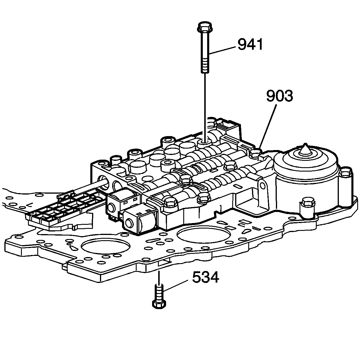
- Install the remaining bolts (941) into the lower control valve body (903).
Tighten
Tighten the bolts (941) to 8-14 N·m (6-19 lb ft).

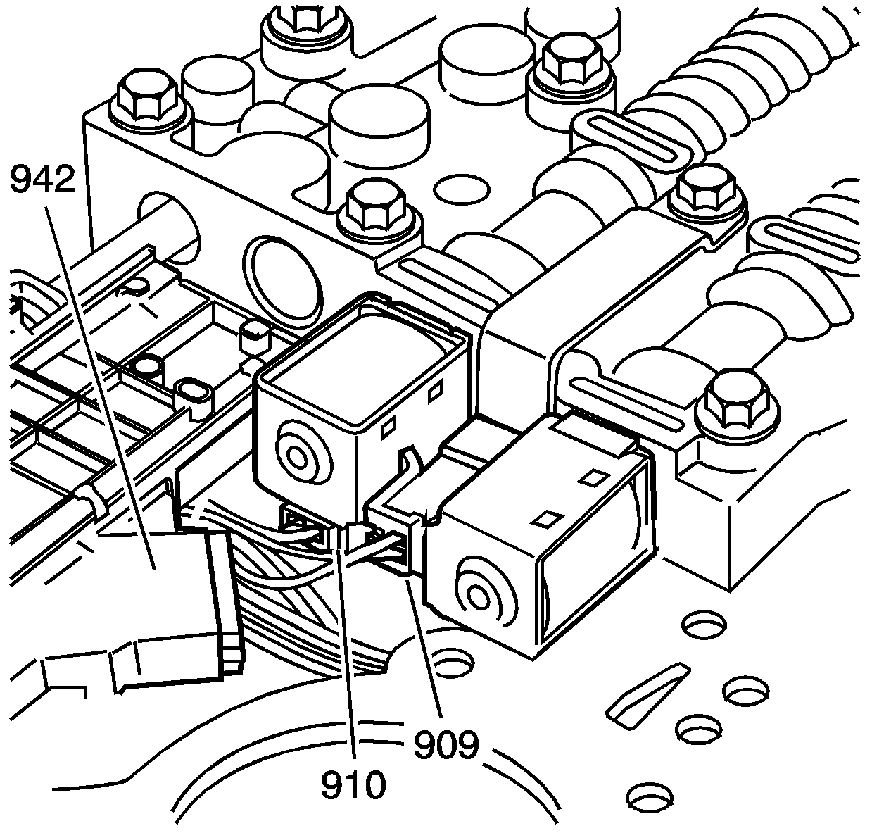
- Connect the lower control valve body wire harness (943) to the following parts:
| • | 1-2 shift solenoid valve (909) |
| • | 2-3 shift solenoid valve (910) |
| • | Internal mode switch (IMS) (942) |


