For 1990-2009 cars only
Removal Procedure
- Raise the vehicle and support it properly. Refer to Lifting and Jacking the Vehicle.
- Remove the front wheel. Refer to Tire and Wheel Removal and Installation.
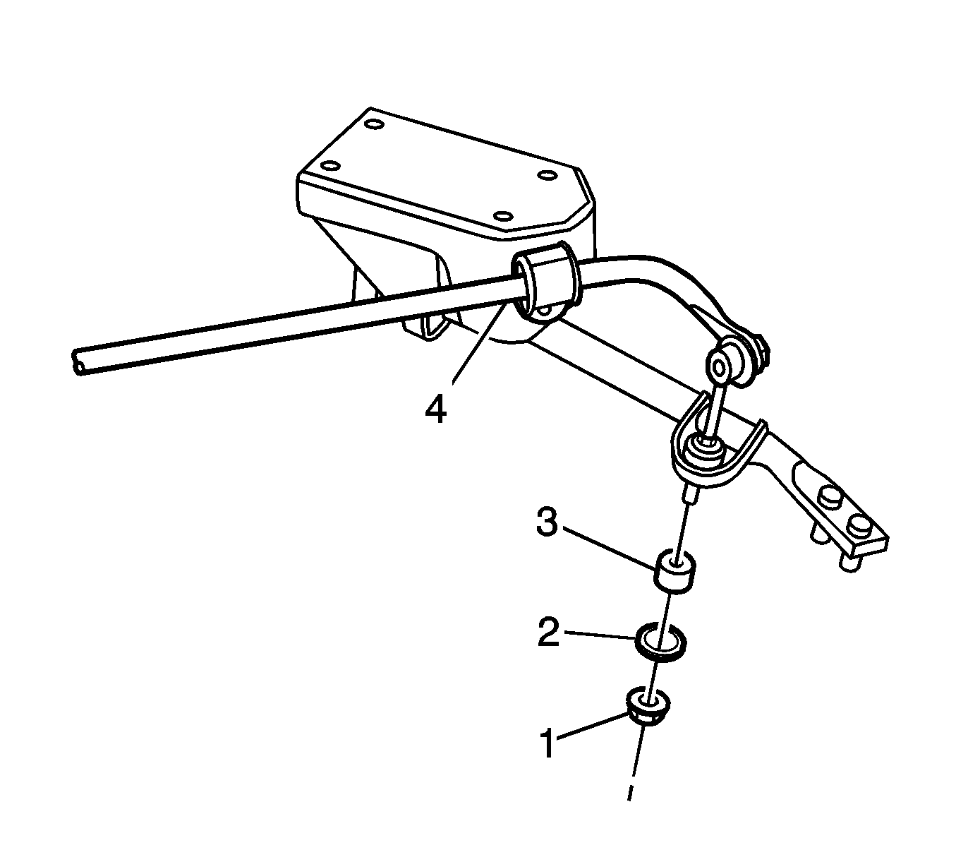
- Remove the mounting nut (1) under the stabilizer bar ball pin subassembly, and remove the plate (2) and the bushing (3).
- Remove the bolt subassembly (4) at the left/right side stabilizer bar pressing block.
- Remove the stabilizer bar and the stabilizer bar ball pin subassembly.
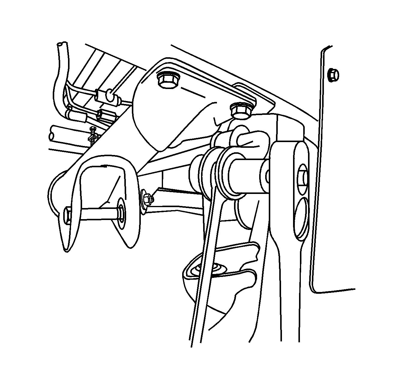
- Remove the stabilizer bar ball pin subassembly. When loosening the nut, use an open wrench with 13 mm opening to hold the ball pin.
Installation Procedure
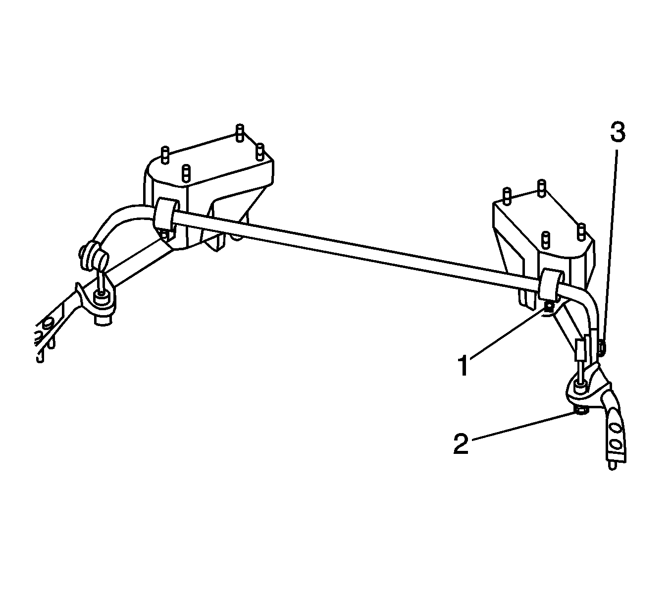
- Install the nut (3) connecting the stabilizer bar ball pin subassembly to the stabilizer bar.
- Install the stabilizer bar ball pin subassembly plate and bushing, and pre-tighten the nut (B) connecting the stabilizer bar ball pin subassembly to the support (1) rod welded unit as shown in figure.
- Install the stabilizer bar bearing and the stabilizer bar pressing block, and pre-tighten the stabilizer bar pressing block mounting nut.
- Install the front wheel and lower the vehicle.
Caution: Refer to Fastener Caution in the Preface section.
Tighten
Tighten the stabilizer bar ball pin subassembly to the stabilizer bar connecting nut (3) to 45-55 N·m.
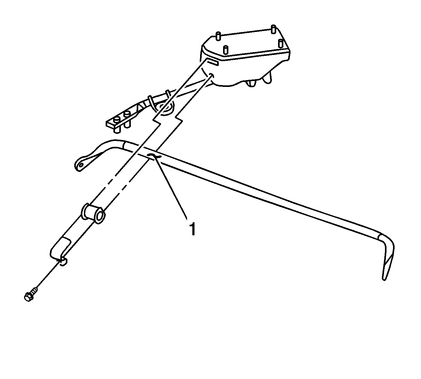
Note: The stabilizer bar bearing should be installed at the white mark on the stabilizer bar.
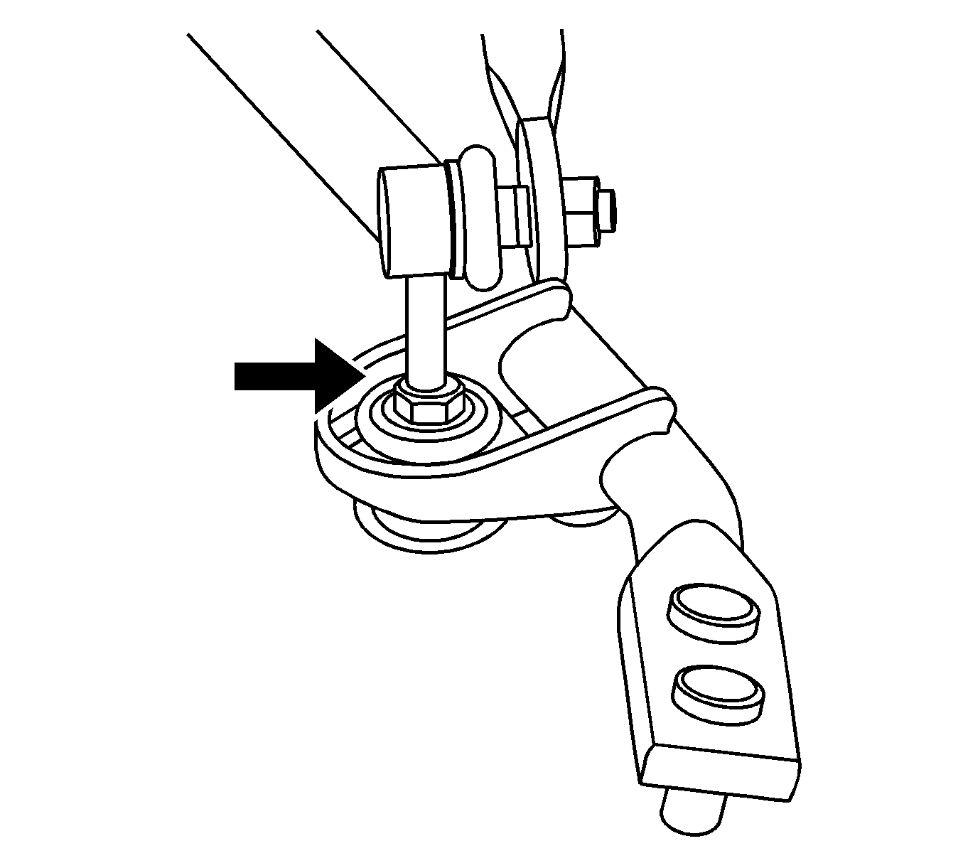
Note: When tightening the nut (B), use an open wrench to secure the hex part at the center of stabilizer bar ball pin subassembly. After tightening, the ball pin dust boot should be aligned with the stabilizer bar connecting part surface (as shown in figure).
With no load on the vehicle, tighten the following bolts to the specified torque:
Tighten
| • | Tighten the stabilizer bar ball pin subassembly to the support rod welded unit connecting nut (B) to 21-25 N·m. |
| • | Tighten the bolt subassembly mounting nuts at the stabilizer bar pressing block to 21-25 N·m. |
