Electronic Suspension Switch Replacement SWBHSV Except Clubsport
Removal Procedure
- Turn the ignition key to the OFF position.
- Remove the Secondary Information Centre (SIC). Refer to Secondary Driver Information Display Replacement .
- Using a suitable tool, disengage the ESC bezel retainer clips (1) from the back of the SIC housing (3) and remove the bezel (2).
- Remove the ESC Switch (4) by disengaging the clips (5) in the rear of the SIC Housing (3) and disconnecting the electrical connectors (6) from the ESC Switch (4) and the ESC Malfunction indicator lamp (7).
Important: The ESC switch is not a serviceable component. If the ESC switch is faulty, replace the ESC switch.
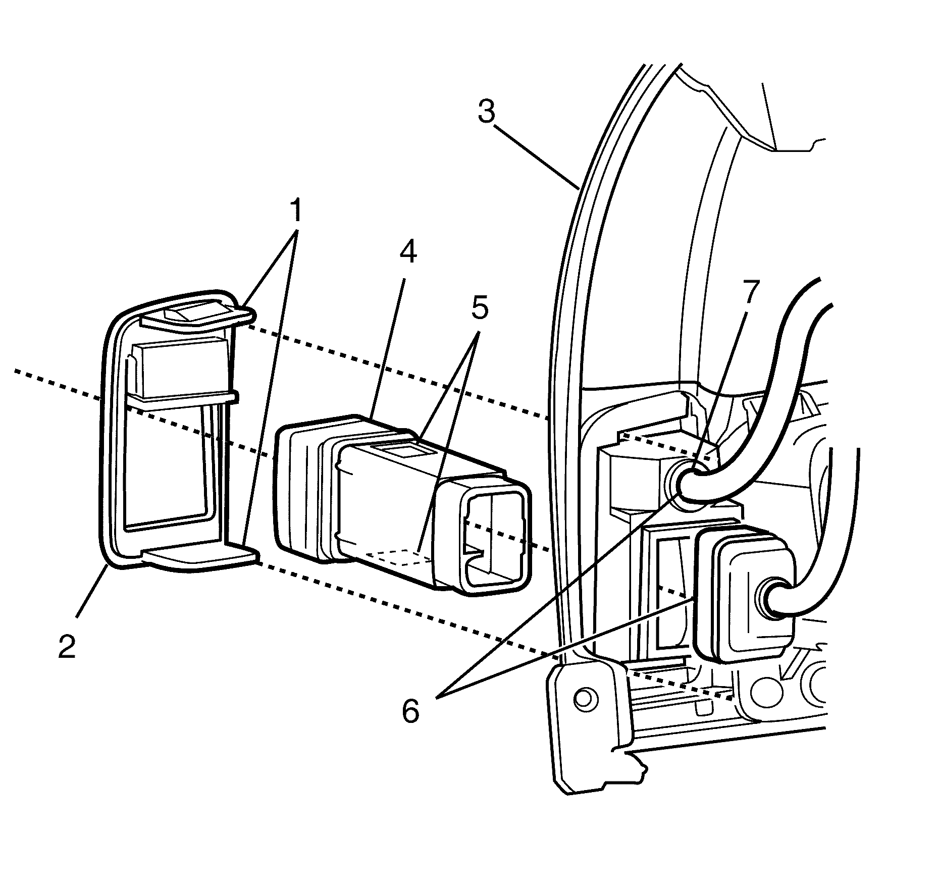
Important: The ESC switch (4) is retained by a bezel (2).
Installation Procedure
- Connect the electrical connectors (6) through the SIC Housing (3) into the ESC Switch (4) and the ESC Malfunction Indicator lamp (7).
- Install the ESC switch by engaging the retention clips (5) on the ESC switch (4) into the SIC housing (3).
- Install the ESC switch bezel (2) into the SIC housing (3) engaging the retention clips (1)
- Ensure the ESC switch bezel (2) is installed flush with the front face of the SIC housing (3).
- Install the SIC. Refer to Secondary Driver Information Display Replacement .
- Test the ESC system.

Important: The ESC switch is not a serviceable component. If the ESC switch is faulty, replace the ESC switch.
Important: The indicator lamp will stay illuminated for a short time after the ignition has been switched off.
Electronic Suspension Switch Replacement LWBHSV
Removal Procedure
- Turn the ignition key to the OFF position.
- Disconnect the battery ground negative. Refer to Battery Negative Cable Disconnection and Connection in Engine Electrical.
- Grasp the front floor console front cover (1) at point (A) and pull upwards to disengage the retaining clips from the floor console (2).
- Disconnect the window and exterior mirror switch electrical connectors (2).
- Disconnect the Traction Control/ESP and Automatic Transmission Sport Shift switch (if fitted) electrical connectors (3).
- Remove the front floor console front cover (1).
- Remove the ESC switch console retaining screws (1) and move the ESC console (2) in an upwards motion.
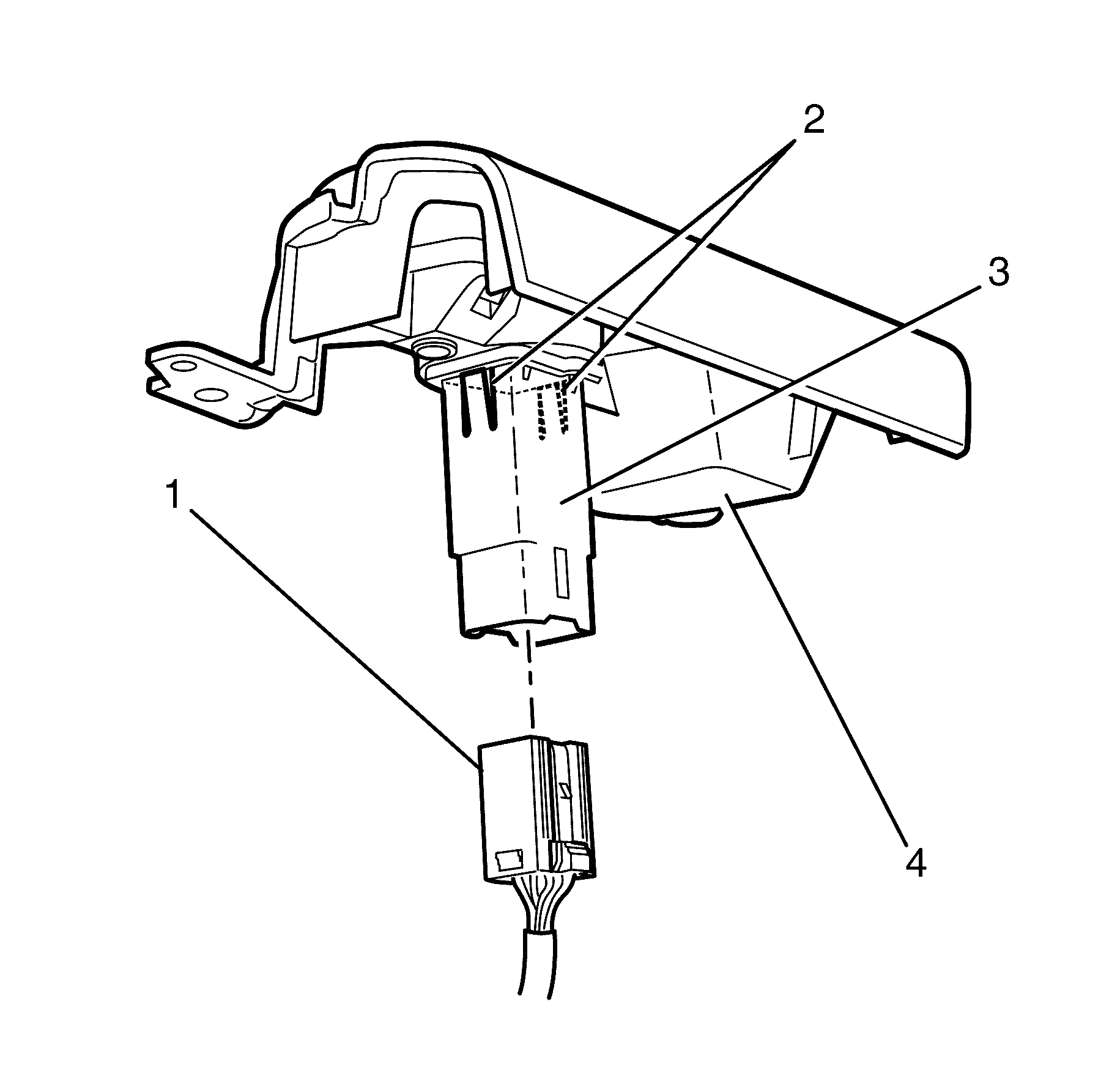
- Disconnect the ESC switch electrical connector (1).
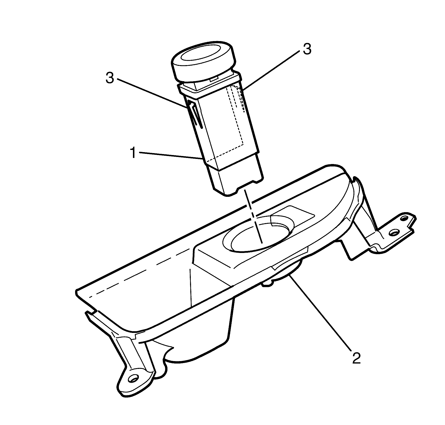
- Depress the locating clips (2) to release the ESC switch (3) from the ESC console (4).
- Remove the ESC Switch (1) from the ESC console (2) by pushing in an upwards motion once the locating clips (3) have been released (STEP 9).
Important: The internal components of the ESC switch are not serviceable. If the ESC switch is faulty, replace the ESC switch.
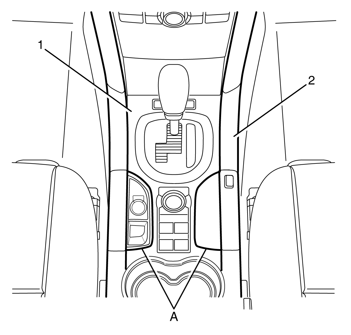
Important: The front floor console front cover (1) is retained by clips.
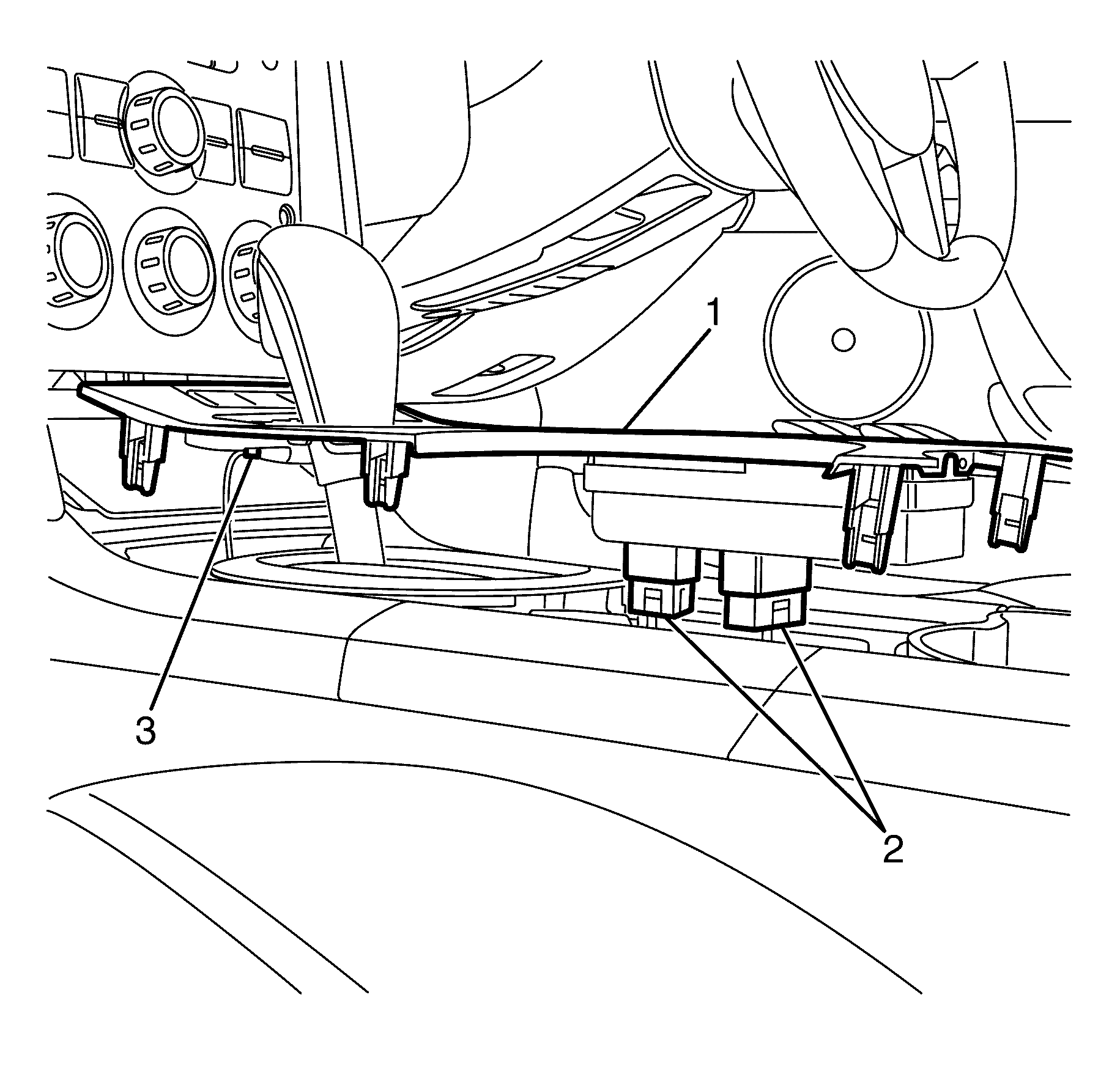
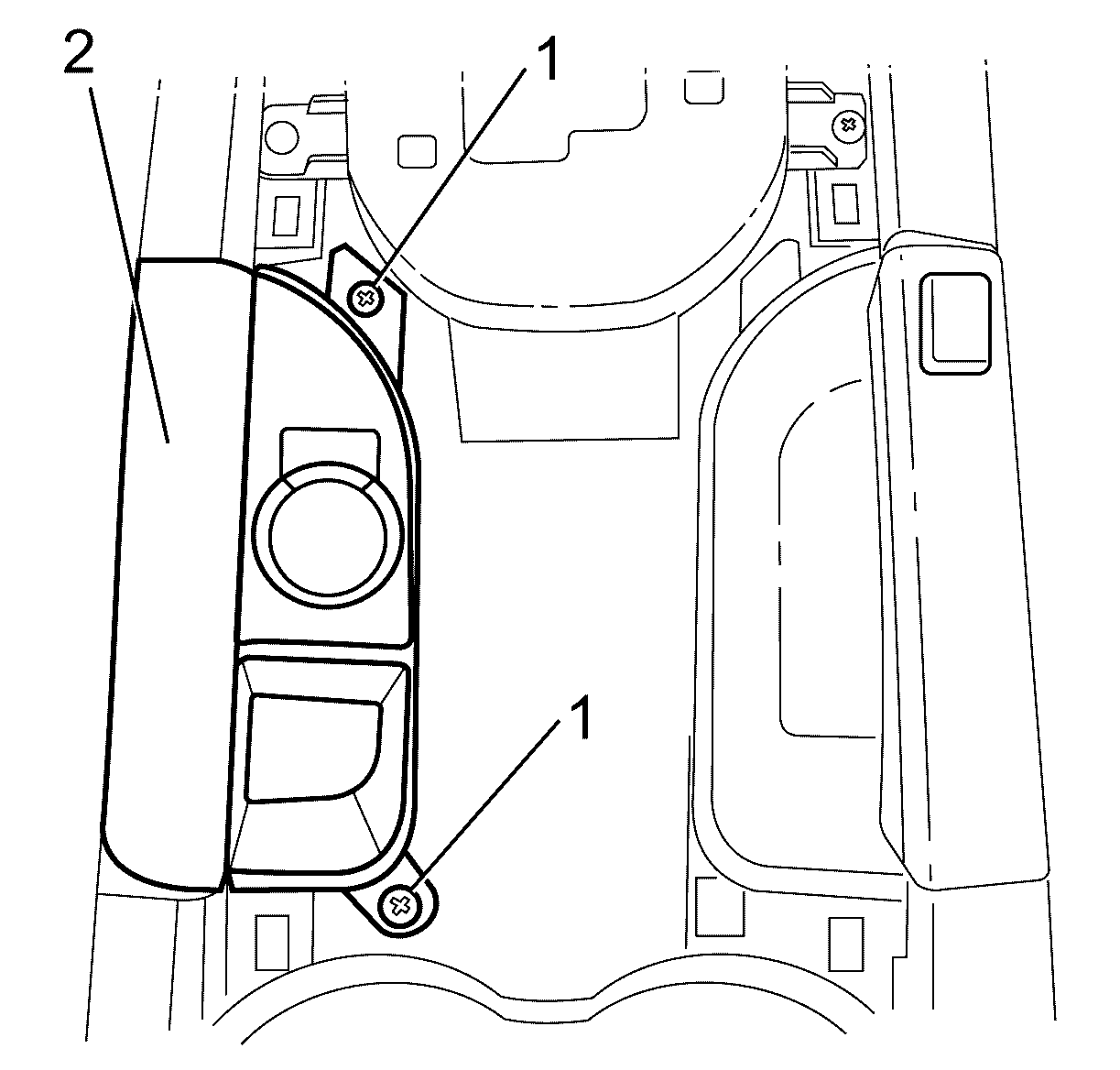
Important: The ESC malfunction indicator lamp is located forwards of the ESC switch under the plate marked MRC. It is not a serviceable component.
Important: The ESC switch is not a serviceable component. If the ESC switch is faulty, replace the ESC switch.
Installation Procedure
- Install the ESC Switch (1) into the ESC console (2) by engaging the clips (3) while pushing in a downward motion.
- Ensure the ESC switch (3) is correctly retained by the locating clips (2) and is engaged into the ESC console (4).
- Connect the ESC switch electrical connector (1).
- Install the ESC switch console (2) .
- Install the ESC switch console retaining screws (1)
- Connect the window and exterior mirror switch electrical connectors (2).
- Connect the Traction Control/ESP and Automatic Transmission Sport Shift switch (if fitted) electrical connectors (3).
- Install the front floor console front cover (1).
- Install the front floor console front cover (1) onto the floor console (2) engaging the retention clips.
- Connect the battery ground negative. Refer to Battery Negative Cable Disconnection and Connection in Engine Electrical.
- Test the ESC system.
Important: The ESC switch is not a serviceable component. If the ESC switch is faulty, replace the ESC switch.


Tighten
Tighten the screws to 2 Nm (18 lb in).


Important: The front floor console front cover (1) is retained by clips.
Important: The indicator lamp will stay illuminated for a short time after the ignition has been switched off.
