For 1990-2009 cars only
Removal Procedure
- Remove the hinge pillar trim from the vehicle. Refer to Body Hinge Pillar Trim Panel Replacement .
- Remove the knee bolster assembly. Refer to Knee Bolster Replacement .
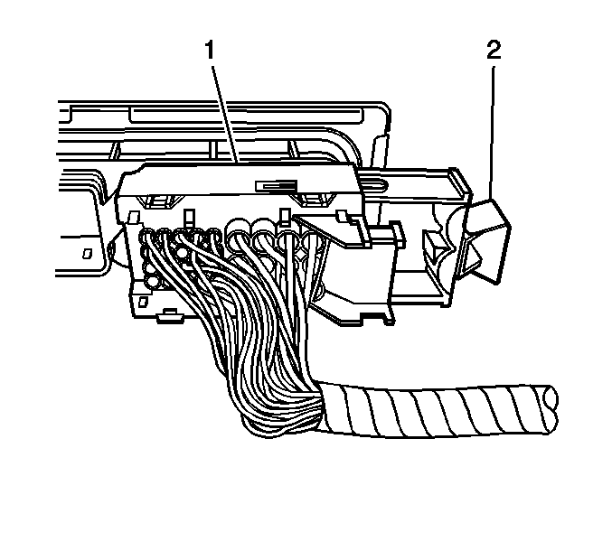
- Unlock the transmission control module electrical connector by pulling the retainer (2) away from the electrical connector (1).
- Carefully disconnect the electrical connector (1) from the transmission control module.
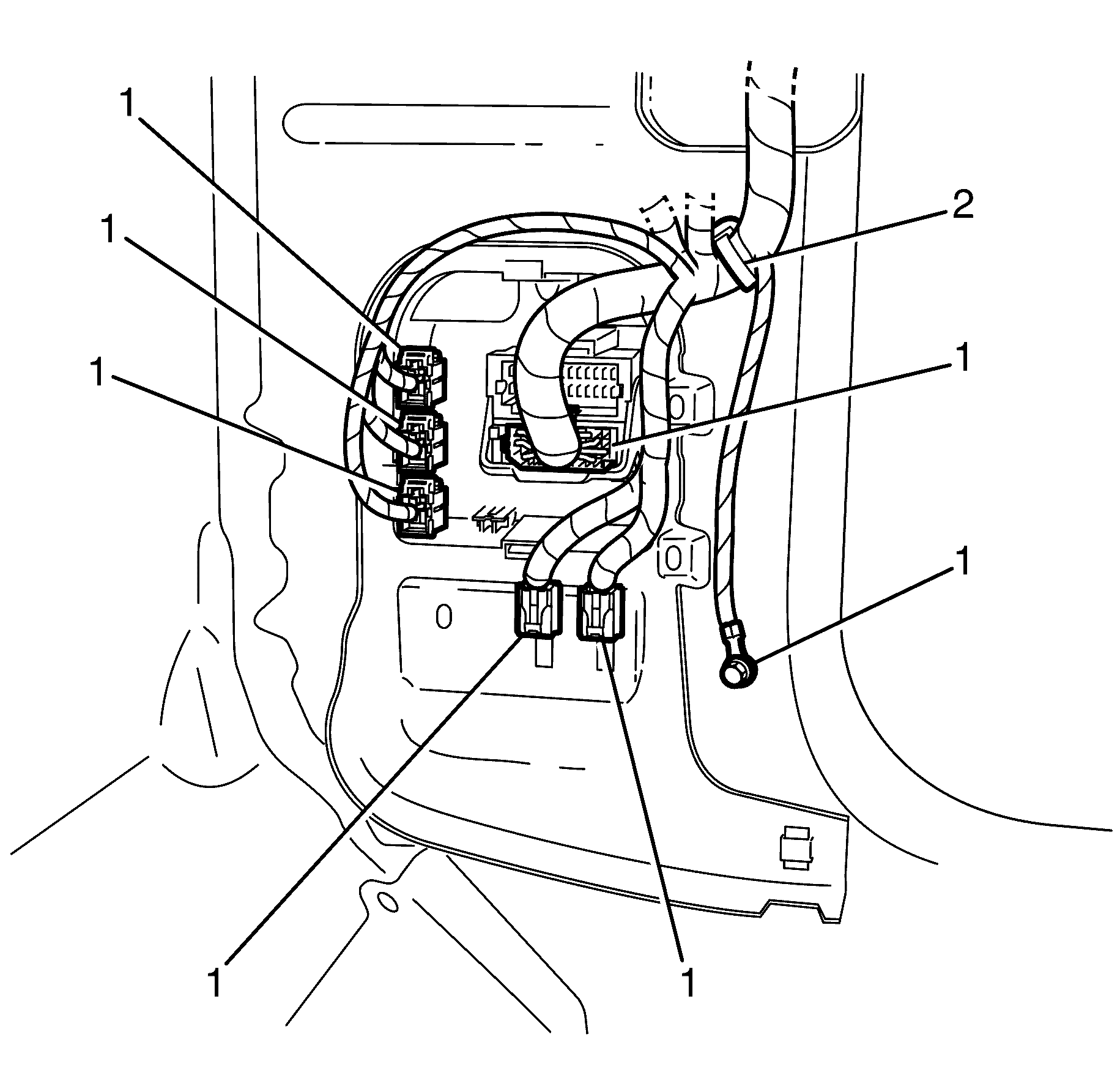
- Disconnect the electrical connectors (1) from right hand side junction box and position loom toward cowl
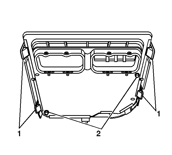
- Remove the transmission control module from the mounting bracket by pulling back on the retaining tabs (1) to release the control module .

Important: Twisting or tilting of the transmission control module electrical connector while disconnecting may result in bent or misaligned electrical terminal pins.


Installation Procedure
- Align the transmission control module with the locating pins (2) on the module mounting bracket.
- Install the transmission control module by seating it fully into the bracket until all of the retaining tabs (1) have engaged the edge of the module edge.
- Install connectors into the right hand side junction box
- Carefully connect the transmission control module electrical connector (1) to the transmission control module.
- Lock the transmission control module electrical connector securely to the transmission control module by pushing the retainer (2) toward the electrical connector (1) until fully seated.
- Install the hinge pillar trim on the vehicle. Refer to Body Hinge Pillar Trim Panel Replacement .
- Install the knee bolster assembly. Refer to Knee Bolster Replacement .
- The transmission control module must be programmed with the proper software/calibrations. Refer to Service Programming System (SPS) .
- Reset the TAP values. Refer to Transmission Adaptive Functions .


Important: Twisting or tilting of the transmission control module electrical connector while connecting may result in bent or misaligned electrical terminal pins.
Important: It is recommended that transmission adaptive pressure (TAP) information be reset.
Resetting the TAP values using a scan tool will erase all learned values in all cells. As a result, The ECM or TCM will need to relearn TAP values. Transmission performance may be affected as new TAP values are learned.