For 1990-2009 cars only
- Clean all parts in a suitable cleaning fluid and dry.
- Inspect the power steering pump drive shaft (2) for:
- Inspect the pump rotor (4) for:
- Inspect the vanes (5) for:
- Inspect the thrust plate (1) for wear and any scoring marks (2).
- Inspect the power steering pump ring (1) for excessive wear and scouring on the inner surface (3) and the side faces (3).
- Inspect the rear end plate (1) for:
- Inspect the power steering pump housing (3) for:
- Inspect the high pressure outlet fitting for:
- Inspect the droop flow control valve for:
Caution: Refer to General Repair Instructions in the Preface section.
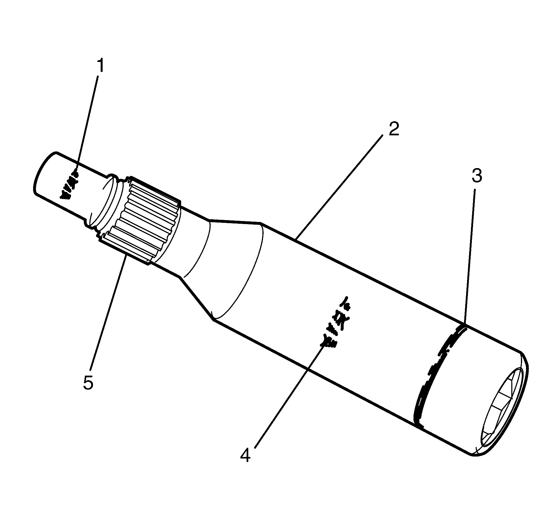
| • | Scoring, pitting or bush pick-up on the pump housing bush surface (1). |
| • | Worn or damaged splines (5). |
| • | Scoring, pitting or bush pick-up on the rear end plate bush surface (4). |
| • | Excessive wear on the seal track (3). |
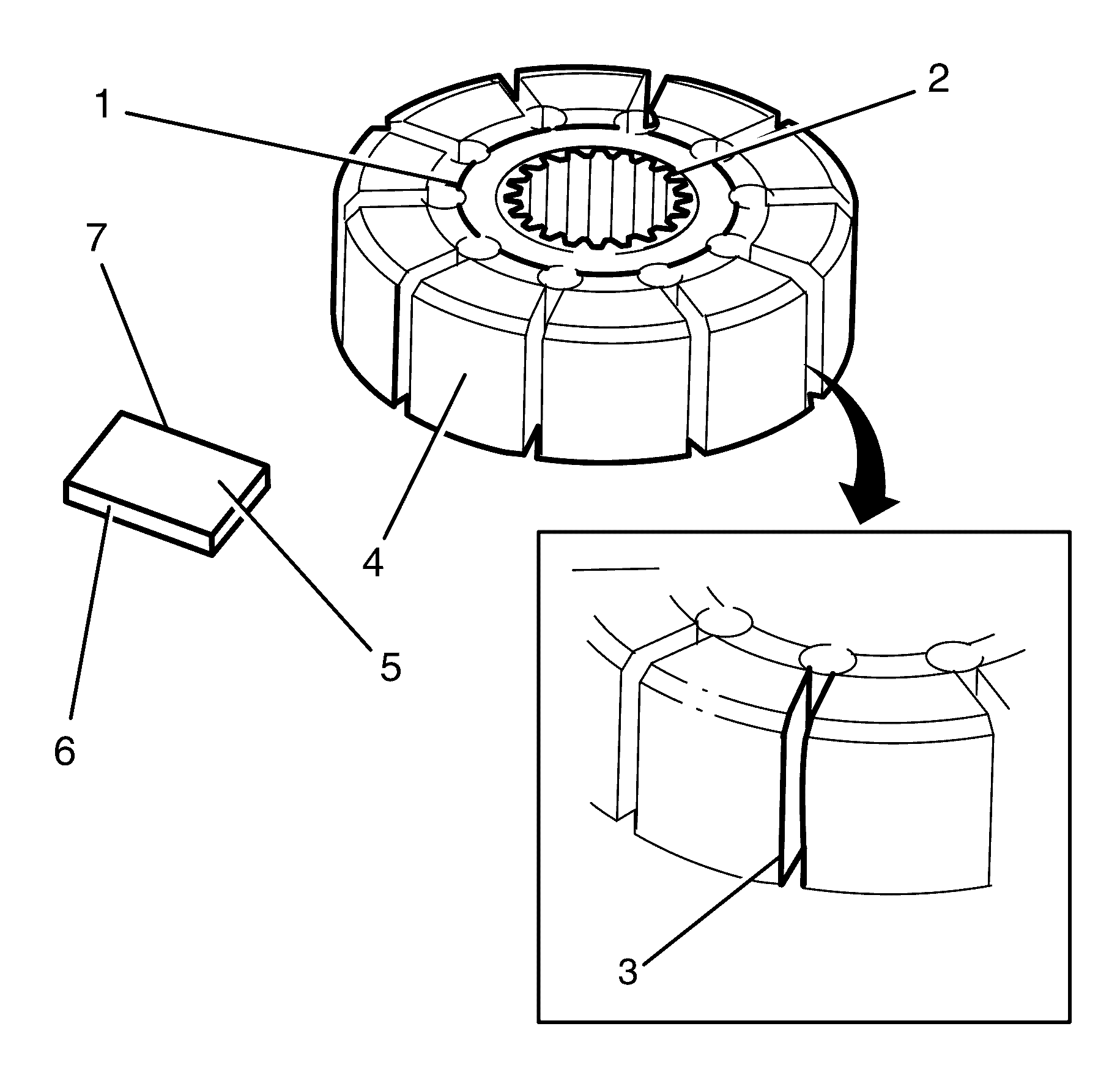
| • | Scoring on the thrust surfaces (1). |
| • | Worn or damaged splines (2). |
| • | Damage to the vane channels (3) that may cause the vanes to stick. |
| • | Excessive wear on the contact surface (7). |
| • | Wear on the thrust faces of the vane (6). |
| • | Make sure the vanes move freely in the vane channels (3). |
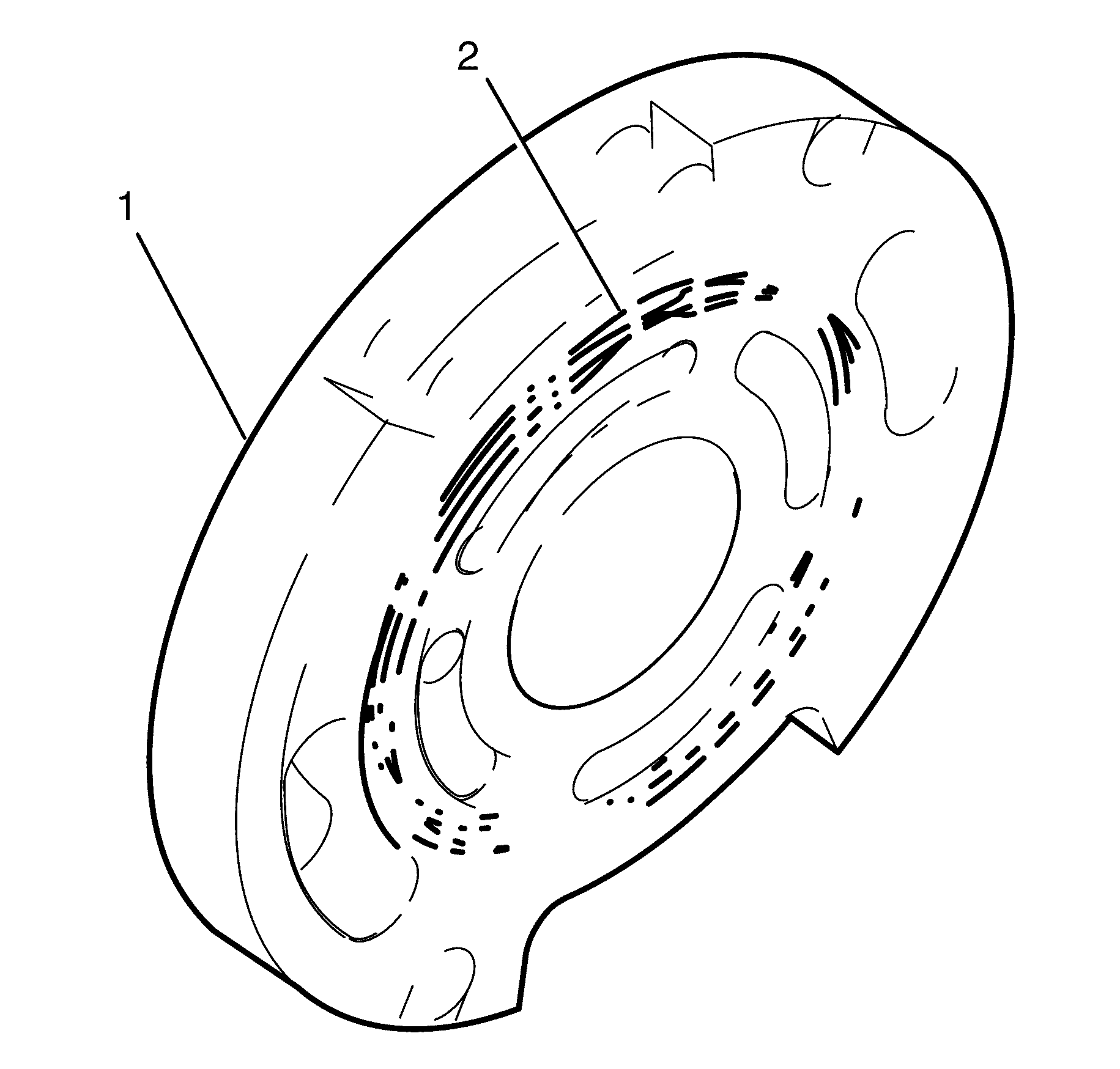
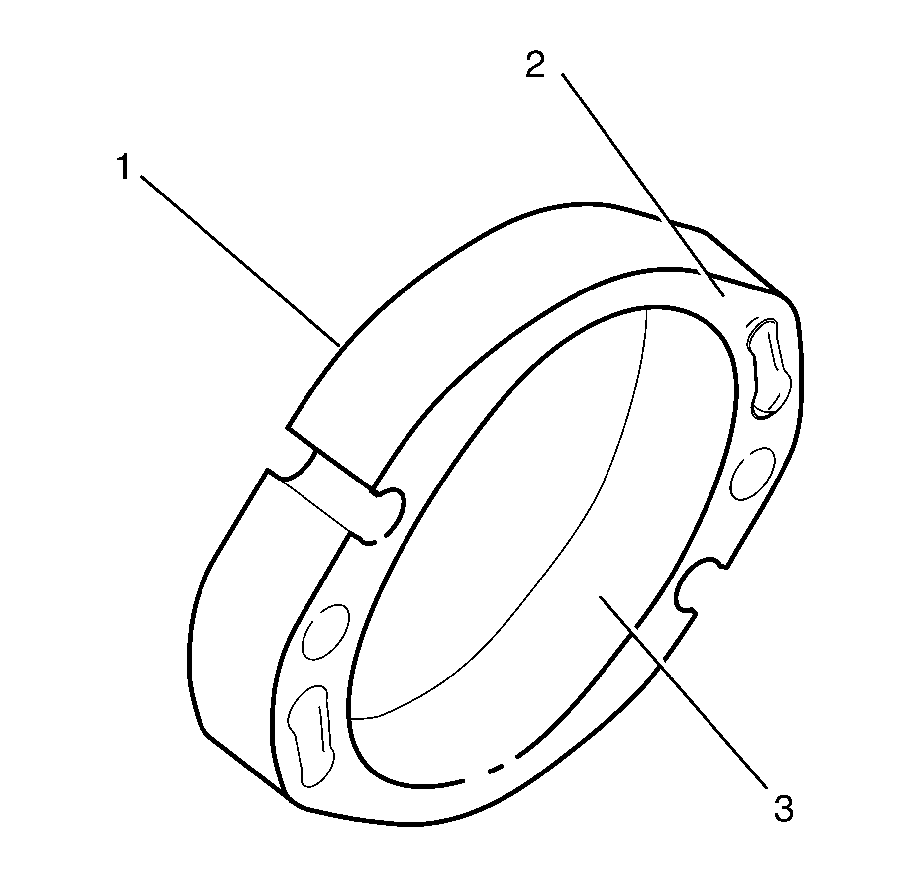
Important: A high polish is always present on the surface of the power steering pump ring as a result of normal wear. Do not confuse this with abnormal wear.
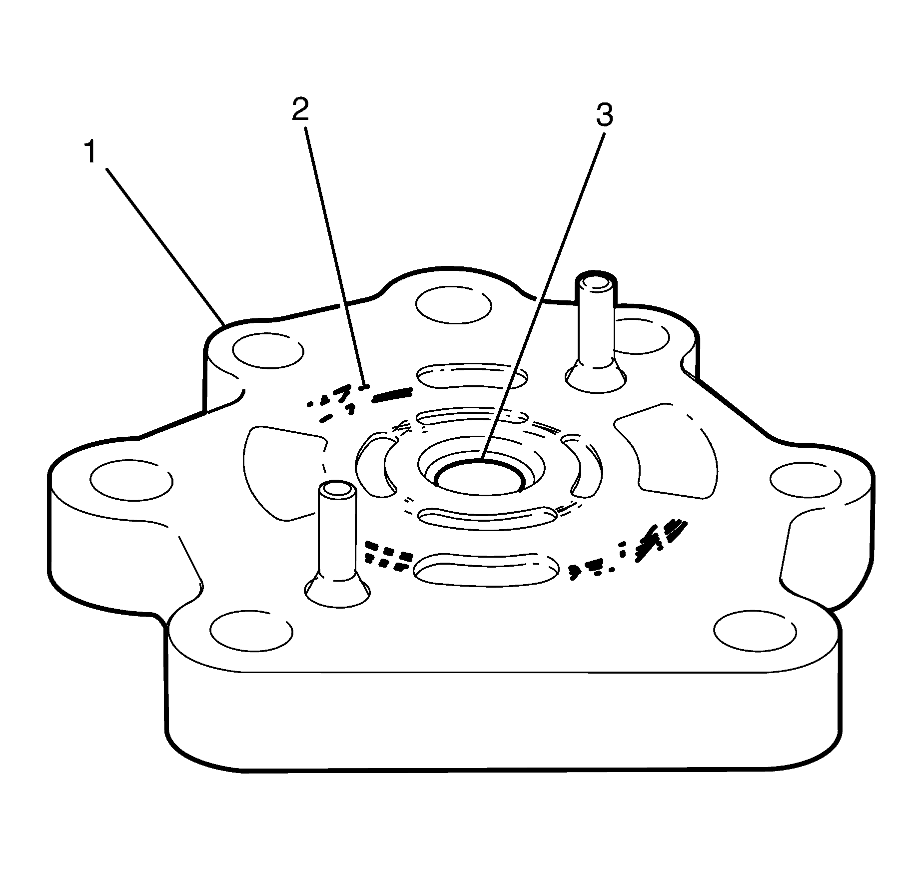
| • | Excessive wear, signs of bush material pick-up or pitting of the rear end plate bush (3). |
| • | Scouring and excessive wear on the thrust face (2). |
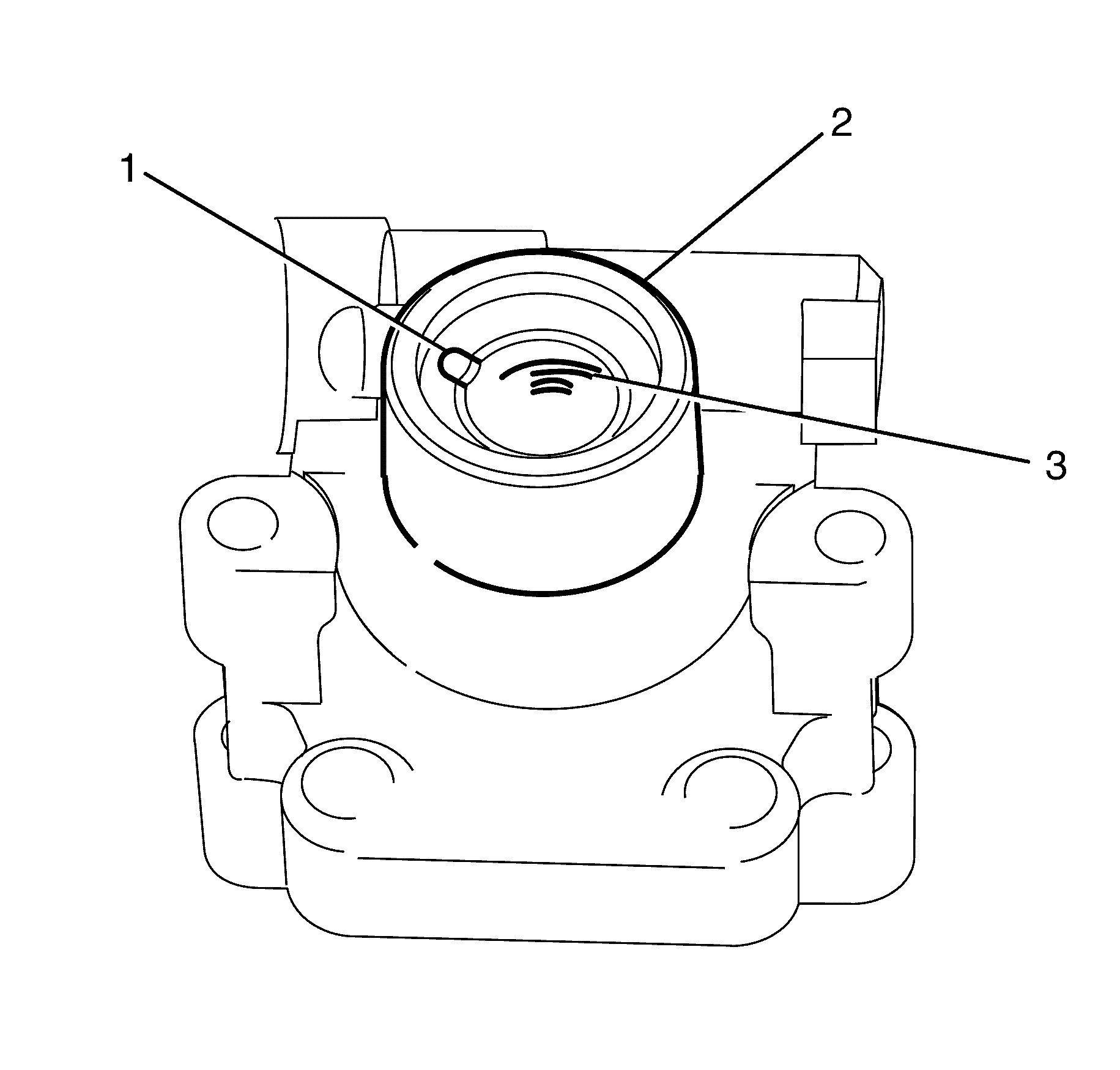
| • | Excessive wear, signs of bush material pick-up or pitting of the power steering pump housing bush (1). |
| • | Blockages in the power steering pump housing bush lubrication passage (2). |
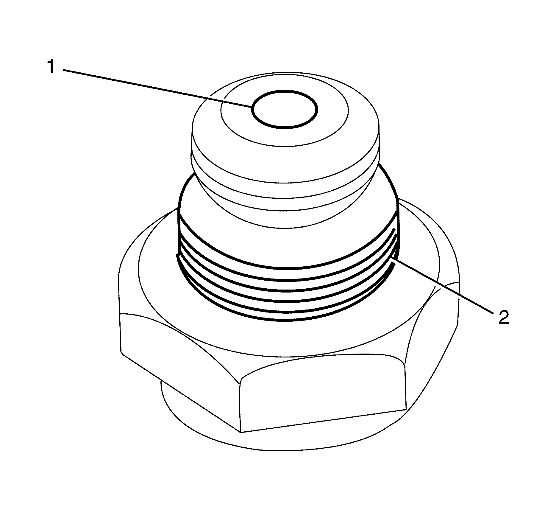
| • | Damage to the threads (2). |
| • | Restrictions in the outlet orifice (1). |
| • | Burrs and foreign material on the shaft and piston plunger. |
| • | Blocked filer screen, which is located in the base of the valve assembly. |
| • | Insert the valve assembly into the pump housing and make sure the valve is free to move in the housing bore. If sticking is observed, check for foreign material and burrs on the inside the housing. |
