For 1990-2009 cars only
Tools Required
J 22610 Installer
Disassembly Procedure
- Remove the rack and pinion steering assembly from the vehicle. Refer to Steering Gear Replacement .
- Remove the valve and pinion assembly from the rack and pinion steering assembly. Refer to Valve and Pinion Assembly Disassemble .
- Remove the rack bearing assembly from the rack and pinion steering assembly. Refer to Rack and Pinion Gear Preload Bearing Replacement .
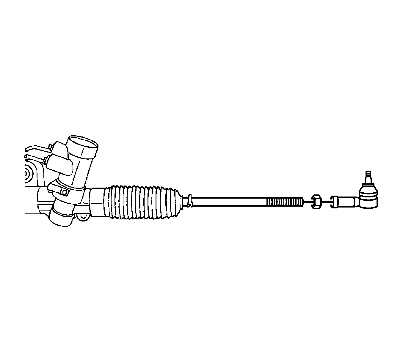
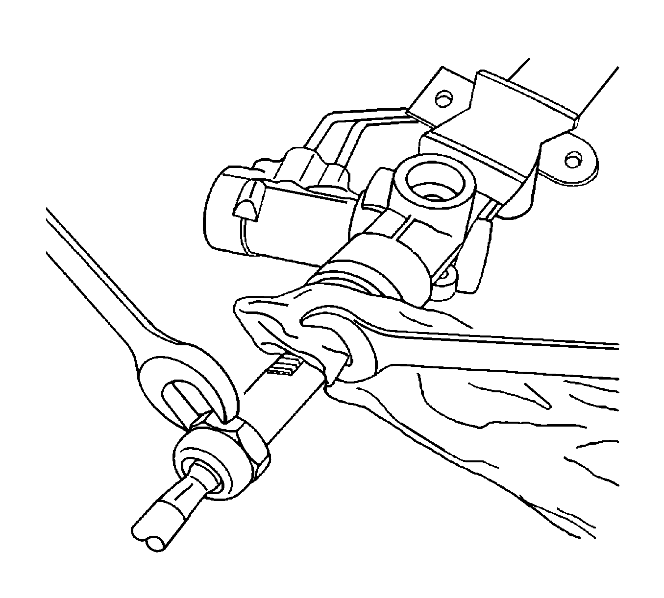
- Mark the threads on the inner tie rod to aid in repositioning the adjusting nut.
- Loosen the adjusting nut and remove the outer tie rod nut and the adjusting nut.
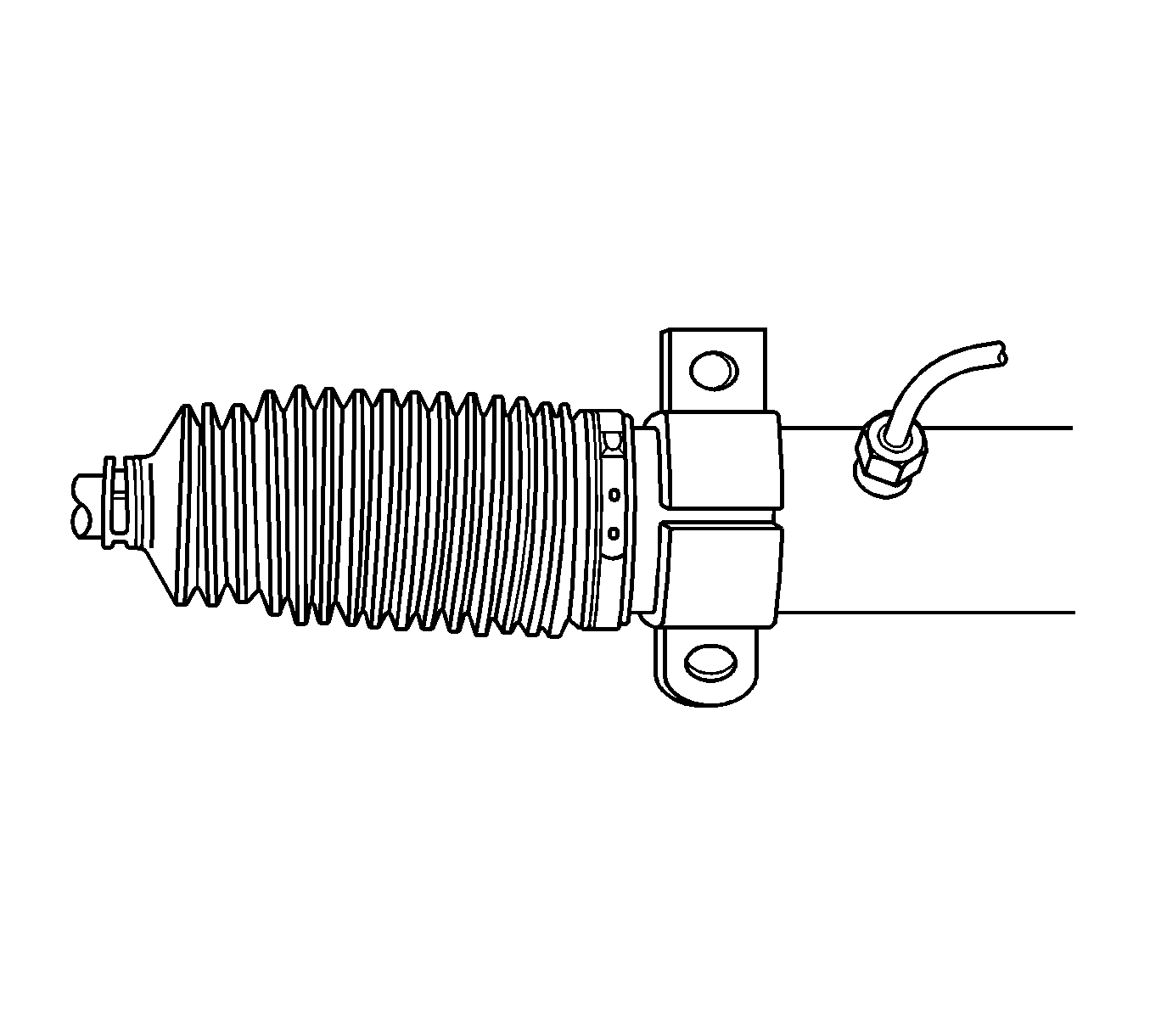
- Remove the dust boot retaining clamps.
- Remove the dust boot.
- Push back the plastic retainer protecting the connection between the inner tie rod and the power steering gear rack.
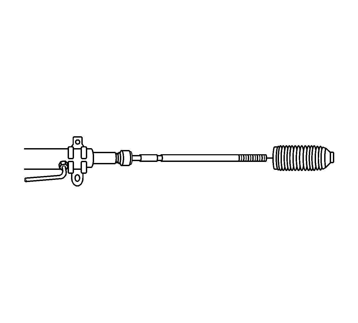
- Counterhold the pinion-side inner tie rod and remove the cylinder-side inner tie rod.
- Place a rag over the rack, counterhold the rack assembly on the teeth with a wrench and remove the pinion-side inner tie rod.
- Remove the bulkhead inner cylinder retaining ring the bulkhead inner cylinder and the rack.
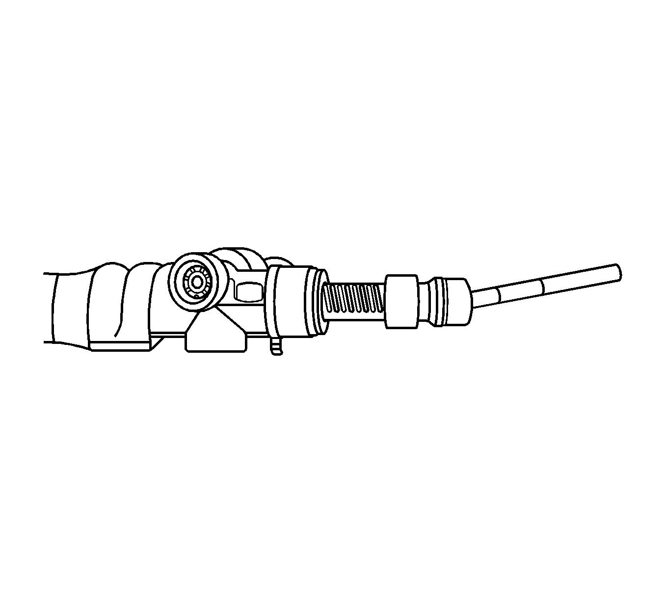
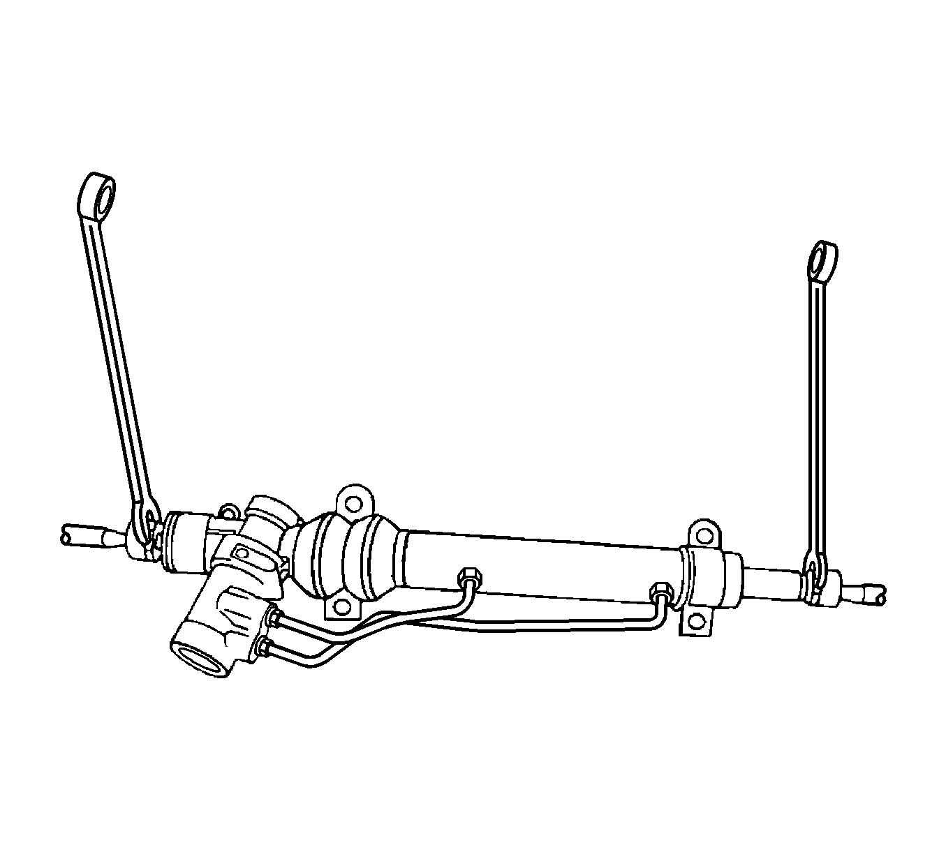
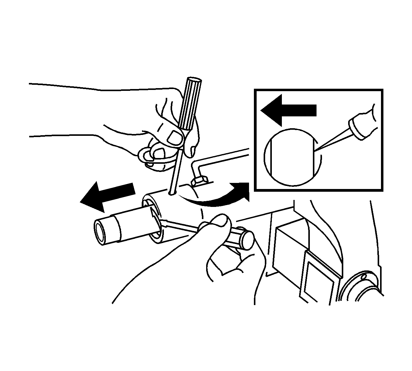
Important: The retaining ring can be released by inserting a small screwdriver through the hole in the side of the housing.
Assembly Procedure
- Install the rack the bulkhead inner cylinder and the bulkhead inner cylinder retaining ring.
- Firmly seat the inner tie rods against the rack and tighten both ends simultaneously.
- Push the plastic retainer back onto the connection between the inner tie rod and the power steering gear rack.
- Install the dust boot.
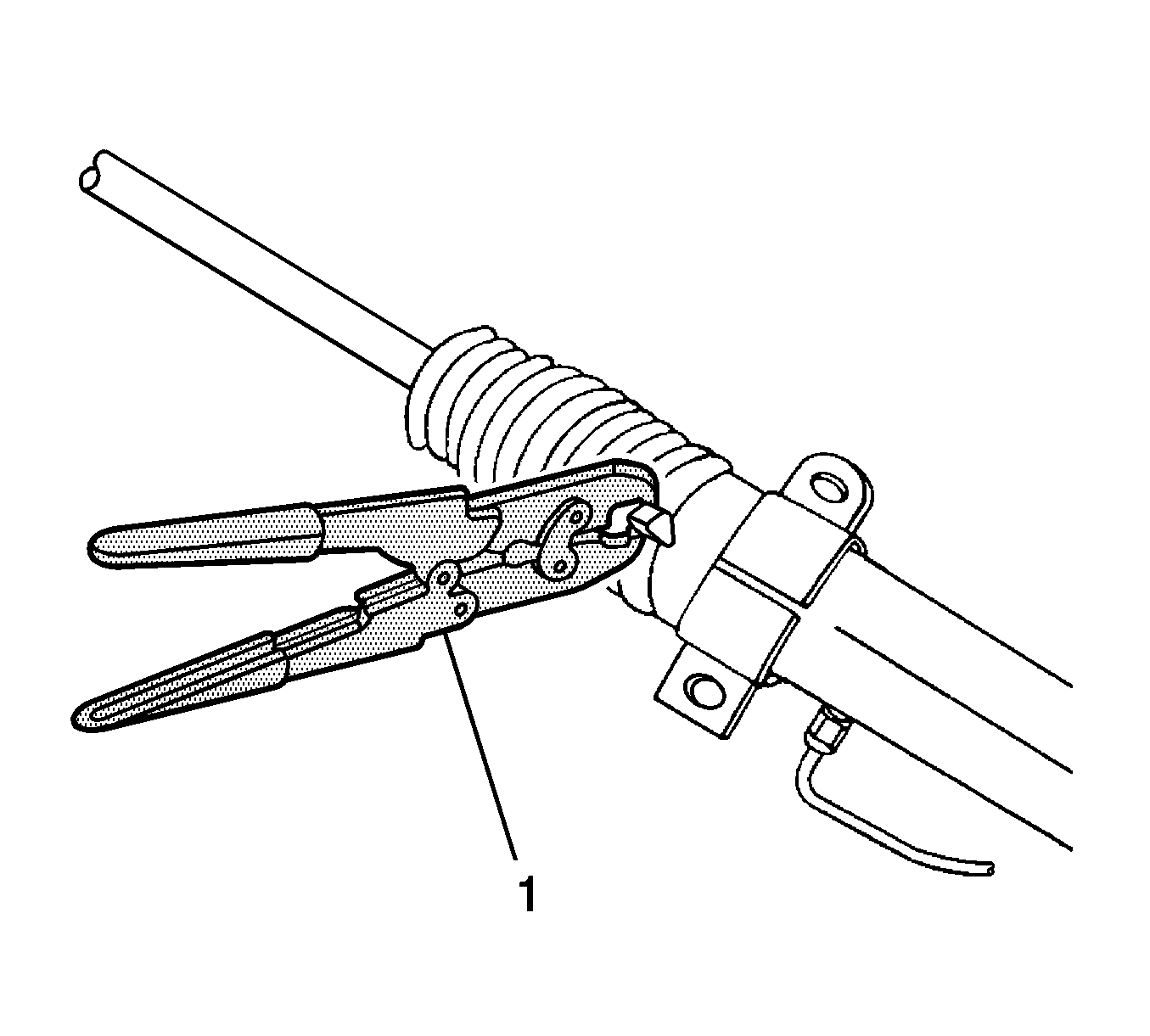
- Install the cylinder end dust boot retaining clamps with J 22610 (1).
- Install the tie rod end boot retaining clamps.
- Reposition the adjusting nut to the marks on the inner tie rod and install the outer tie rod by twisting it onto the inner tie rod.
- Perform a front toe adjustment. Refer to Front Toe Adjustment in Wheel Alignment.
- Install the adjusting nut.
- Install the rack bearing assembly into the rack and pinion steering assembly. Refer to Rack and Pinion Gear Preload Bearing Replacement .
- Install the valve and pinion assembly into the rack and pinion assembly. Refer to Valve and Pinion Assembly Disassemble .
- Install the rack and pinion steering assembly into the vehicle. Refer to Steering Gear Replacement .

Important: Coat all the seals with power steering fluid to ensure proper sealing.

Important: To prevent the inner tie rods from loosening, use Loctite® 242, or equivalent, on both inner tie rod connections to secure them to the rack shaft.
Important: The right and left inner tie rods are unequal in length. Be sure to install the correct inner tie rod on the proper side of the power steering gear.
Tighten
Tighten the inner tie rods to 100 N·m
(74 lb ft).




Notice: Refer to Fastener Notice in the Preface section.
Tighten
Tighten the outer tie rod adjusting nut to 64 N·m
(47 lb ft).
