Inflatable Restraint Sensing and Diagnostic Module Replacement 2.0L
Removal Procedure
- Disable the supplemental inflatable restraints (SIR). Refer to Disabling the SIR System
- Remove the floor console. Refer to Front Floor Console Replacement in Interior Trim.
- Remove the connector position assurance lock, which is tethered to the SDM connector.
- Disconnect the SDM electrical connector.
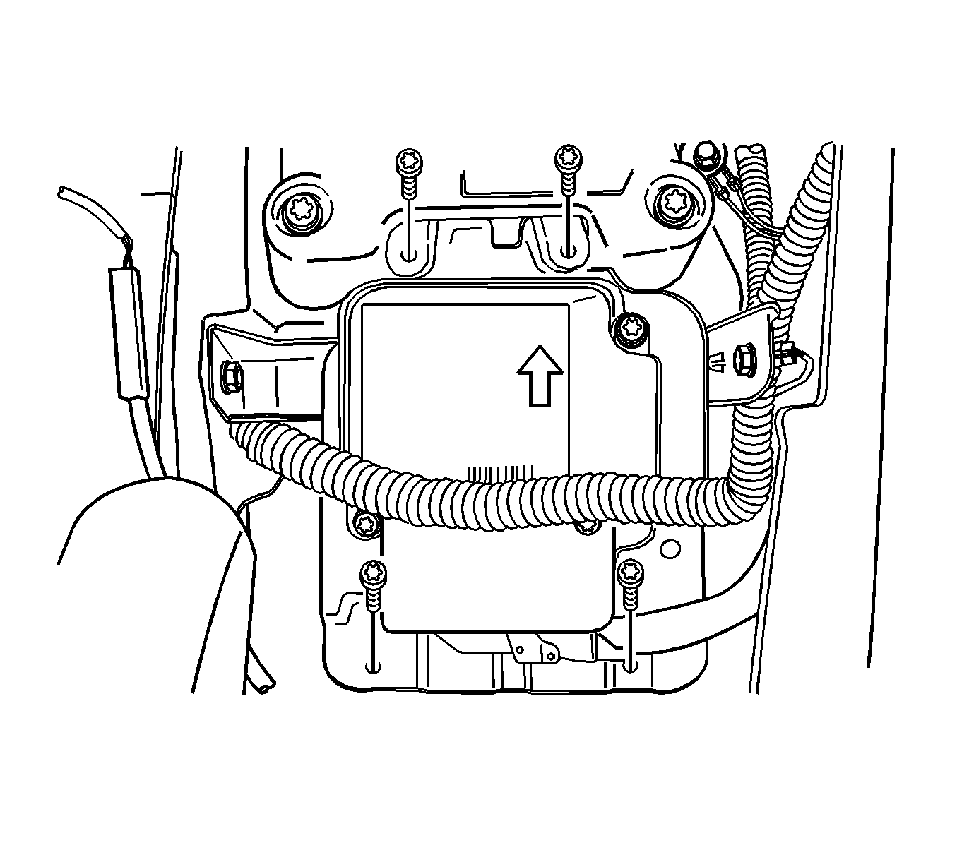
- Remove the SDM mounting bolts.
- Remove the SDM.
Caution: Refer to Sensing and Diagnostic Module Handling Caution in the Preface section.
Caution: Refer to SIR Caution in the Preface section.

Important: If the vehicle interior has been exposed to extensive water intrusion such as water leaks, driving through high water, flooding, or other causes, then the sensing and diagnostic module (SDM) and SDM connector may need to be replaced. With the ignition OFF, inspect the area of SDM, including the carpet. If any significant soaking or evidence of previous soaking is detected, the water must be removed, the water damage repaired, and the SDM and SDM connector must be replaced. Before attempting any of these repairs, the SIR must be disabled. Refer to Disabling the SIR System .
Installation Procedure
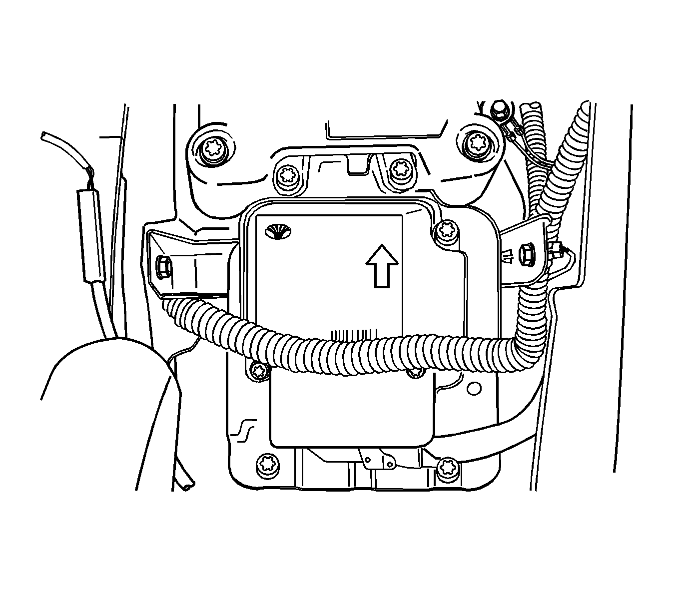
- Install the SDM with the arrow pointing toward the front of the vehicle.
- Install the SDM mounting bolts.
- Connect the SDM electrical connector.
- Install the connector position assurance lock.
- Install the floor console. Refer to Front Floor Console Replacement in Interior Trim.
- Enable the SIR. Refer to Enabling the SIR System .
Caution: Refer to SIR Special Tool Caution in the Preface section.
CAUTION: Be careful when you handle a sensing and diagnostic module (SDM). Do
not strike or jolt the SDM. Before applying power to the SDM:
• Remove any dirt, grease, etc. from the mounting surface • Position the SDM horizontally on the mounting surface • Point the arrow on the SDM toward the front of the vehicle • Tighten all of the SDM fasteners and SDM bracket fasteners to
the specified torque value
Notice: Refer to Fastener Notice in the Preface section.

Tighten
Tighten the SDM mounting bolts to 10 N·m (89 lb in).
Inflatable Restraint Sensing and Diagnostic Module Replacement 1.6/1.8L
Caution: Refer to Sensing and Diagnostic Module Handling Caution in the Preface section.
Important: If the vehicle interior has been exposed to extensive water intrusion such as water leaks, driving through high water, flooding or other causes, then the sensing and diagnostic module (SDM) and SDM connector may need to be replaced. With the ignition OFF, inspect the area of the SDM, including the carpet. If any significant soaking or evidence of previous soaking is detected, the water must be removed, the water damage repaired, and the SDM and SDM connector must be replaced. Before attempting any of these repairs, the supplemental restraint system (SRS) must be disabled. Refer to Disabling the SIR System .
Removal Procedure
- Disable the SIR. Refer to Disabling the SIR System .
- Remove the floor console. Refer to Front Floor Console Replacement in Instrument Panel, Gages, and Console.
- Remove the connector position assurance (CPA) lock, which is tethered to the SDM connector.
- Disconnect the SDM electrical connector.
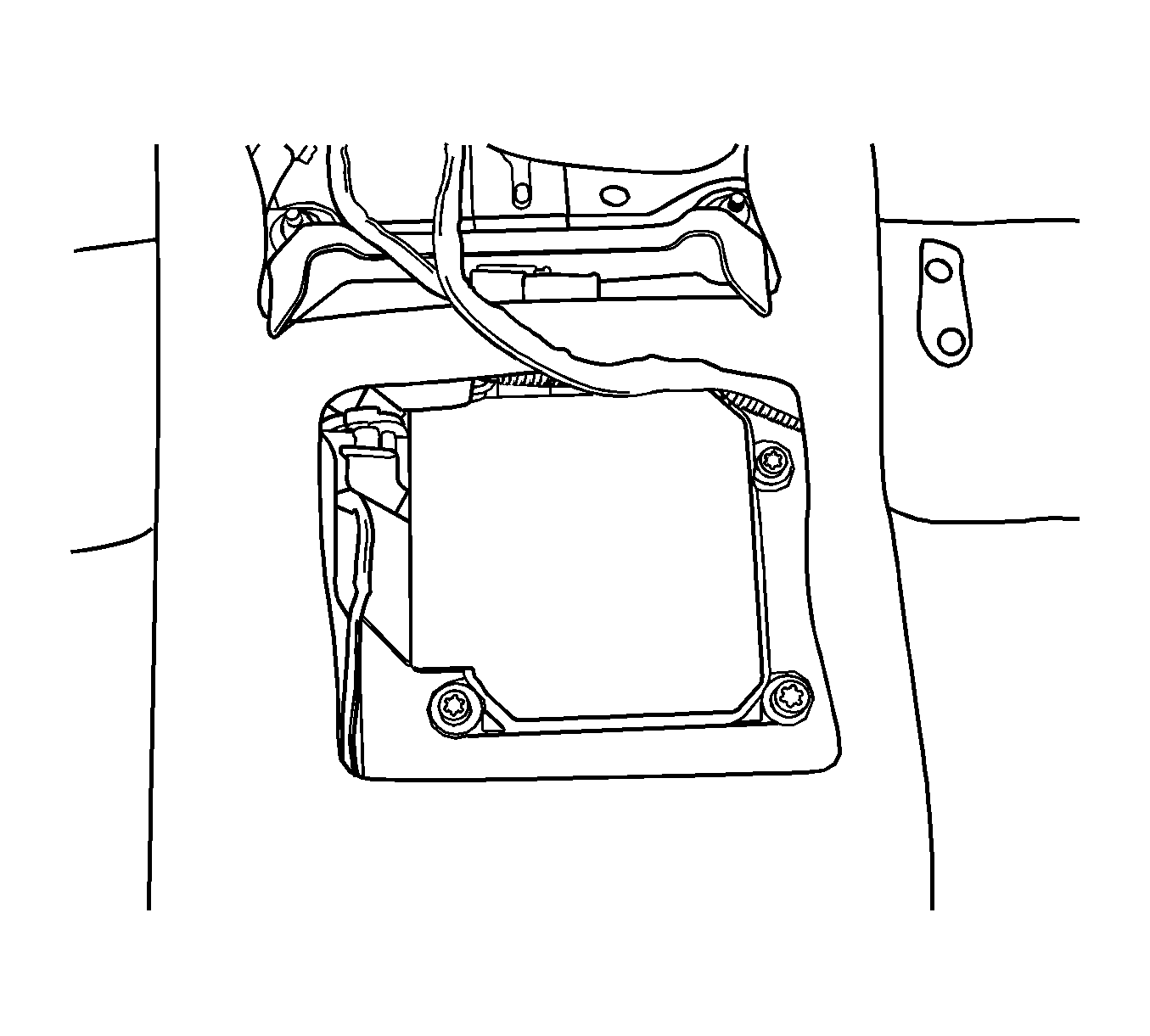
- Remove the SDM mounting bolts.
- Remove the SDM.
Caution: Refer to SRS Handling Caution in the Preface section.

Installation Procedure
- Install the SDM.
- Install the SDM mounting bolts.
- Connect the SDM electrical connector.
- Install the CPA lock, which is tethered to the SDM connector.
- Install the floor console. Refer to Front Floor Console Replacement in Instrument Panel, Gages, and Console.
- Enable the SIR. Refer to Enabling the SIR System .

Caution: Refer to Sensing and Diagnostic Module Handling Caution in the Preface section.
Notice: Refer to Fastener Notice in the Preface section.
Tighten
Tighten the SDM mounting bolts to 10 N·m
(89 lb in).
