For 1990-2009 cars only
Removal Procedure
- Disconnect the negative battery.
- Remove the instrument panel and tie-bar. Refer to Instrument Panel Assembly Replacement in Instrument Panel, Gages and Console.
- Drain the cooling system. Refer to Cooling System Draining and Filling in Engine Cooling.
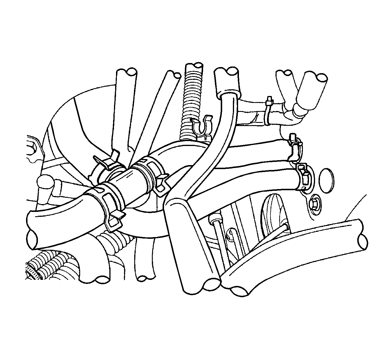
- Compress the heater hose clamps at the cowl and slide the clamps toward the engine.
- Remove the 2 heater hoses from the core pipes and the cowl.
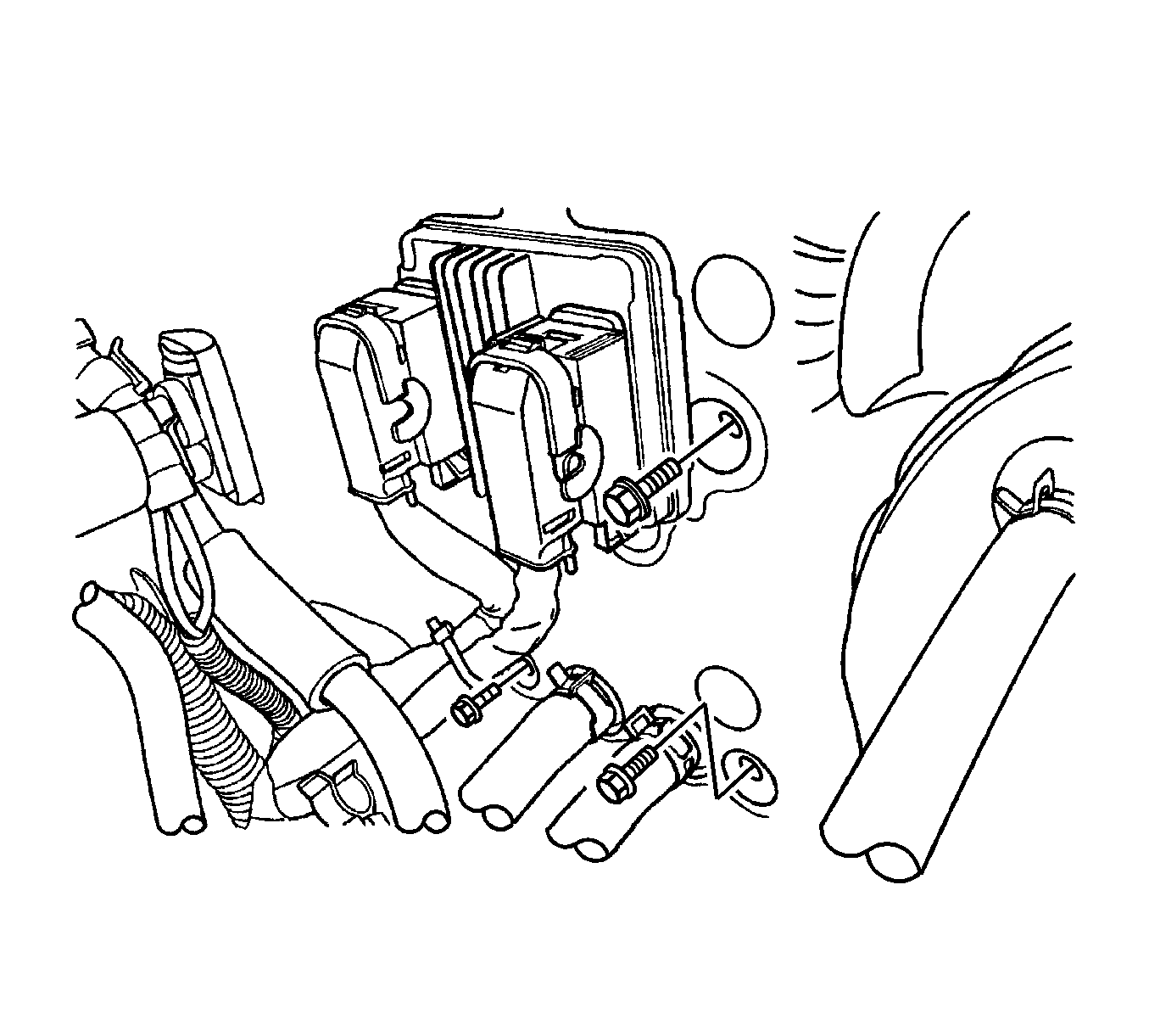
- Remove the screws that secure the heater/air distributor case assembly to the cowl on the side of the heater core pipes.
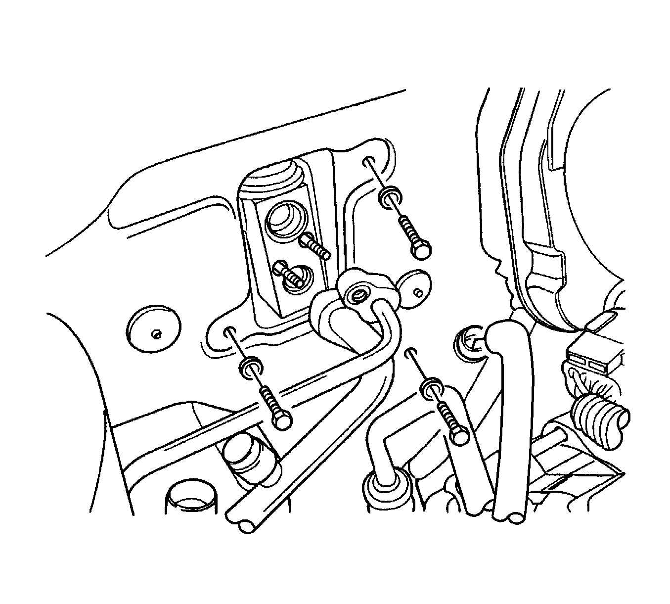
- Remove the high-pressure and low-pressure pipe from the A/C expansion valve.
- Remove the evaporator drain hose.
- Have an assistant support the heater/air distributor case from inside the vehicle.
- Remove the screws that secure the heater/air distributor case assembly to the cowl on the side of the evaporator.
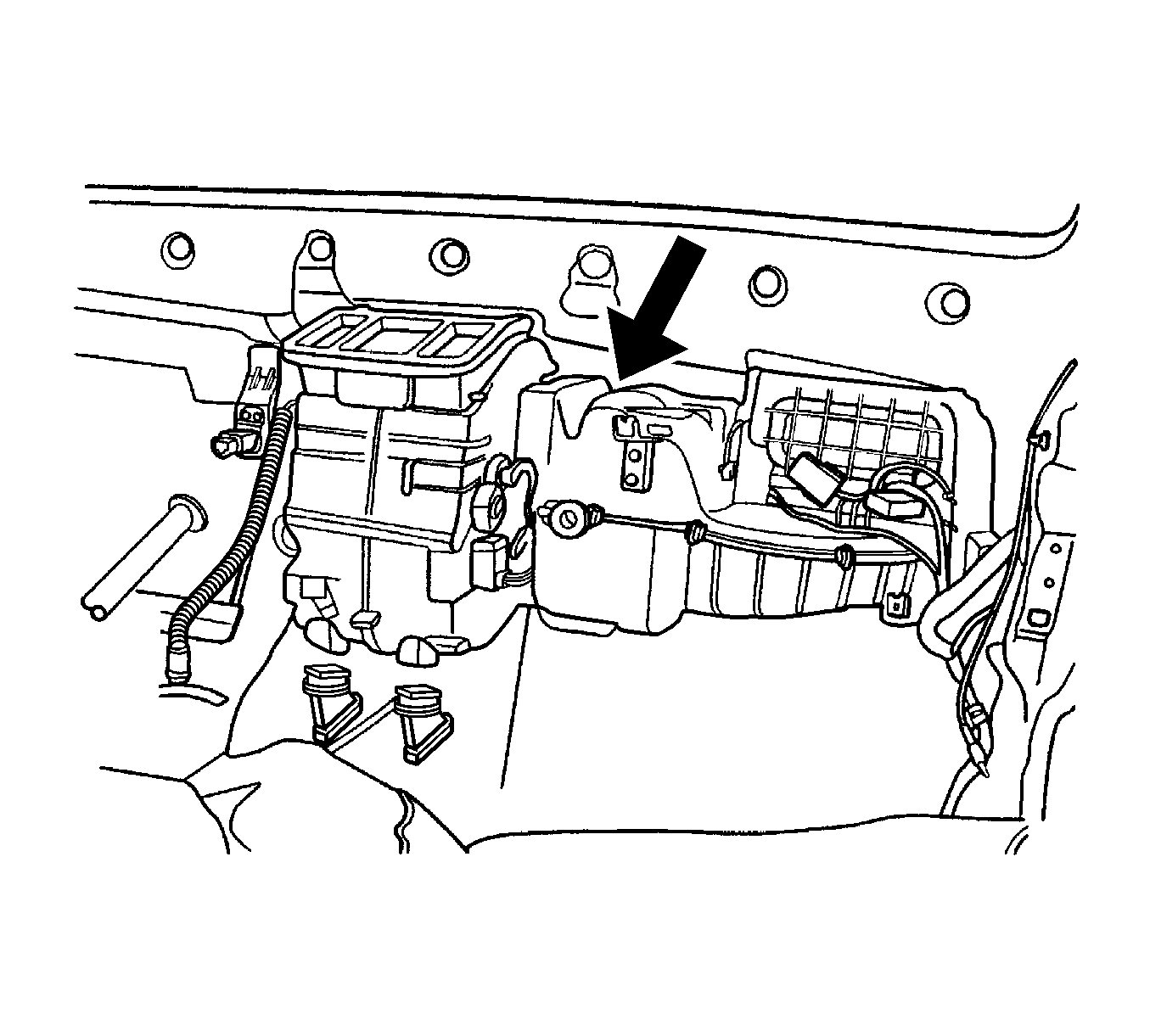
- Disconnect the rear duct connector.
- Remove the heater/air distributor case assembly from the vehicle.
Caution: Refer to Battery Disconnect Caution in the Preface section.
Notice: Use care when handling the heater case to avoid damaging the mode linkage levers.
Installation Procedure
- Position the heat/air distributor case assembly in the vehicle.
- Slowly raise the heater/air distributor case assembly into position against the cowl and hold it in position while the screws are installed and tighten from the engine side of the cowl.
- Install the high pressure and low pressure pipe.
- Install the heater/air distributor case assembly screws at the side of evaporator through the cowl from the engine compartment side.
- Install the heater/air distributor case assembly screws at the side of the heater core pipes through the cowl from the engine compartment side.
- Install the 2 heater hoses.
- Slide the heater hose clamps into position.
- Connect the rear duct connector.
- Install the instrument panel and tie-bar. Refer to Instrument Panel Assembly Replacement in Instrument Panel, Gages and Console.
- Fill the cooling system. Refer to Cooling System Draining and Filling in Engine Cooling.
- Connect the negative battery cable.
- Operate the controls to verify the proper function of the heating and ventilation systems.
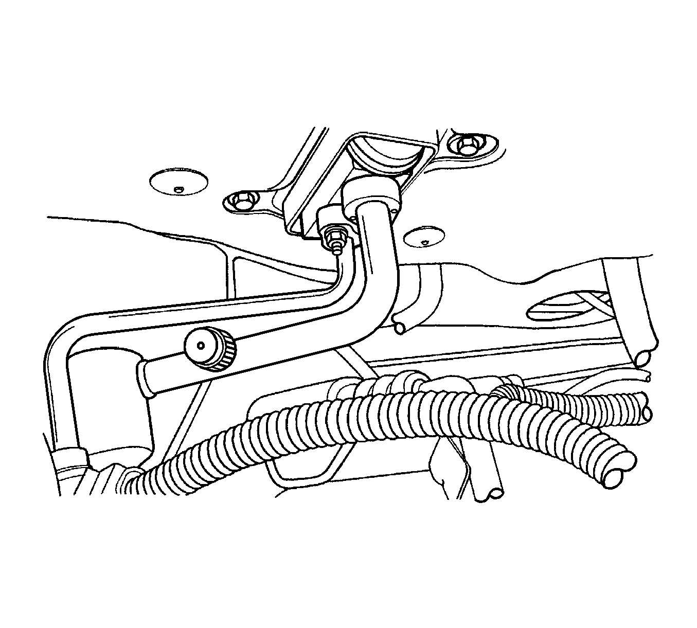
Important: Avoid damaging the heater core pipes by making sure they do not contact the cowl opening.
Notice: Refer to Fastener Notice in the Preface section.
Tighten
Tighten the heater/air distributor case assembly
screws to 4 N·m (35 lb in).
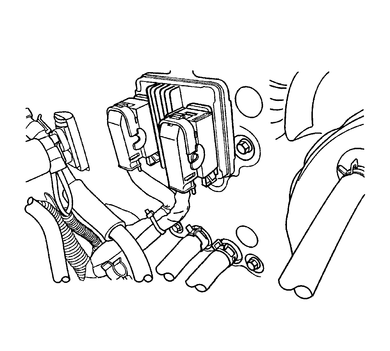
Tighten
Tighten the heater/air distributor case assembly
screws to 4 N·m (35 lb in).
