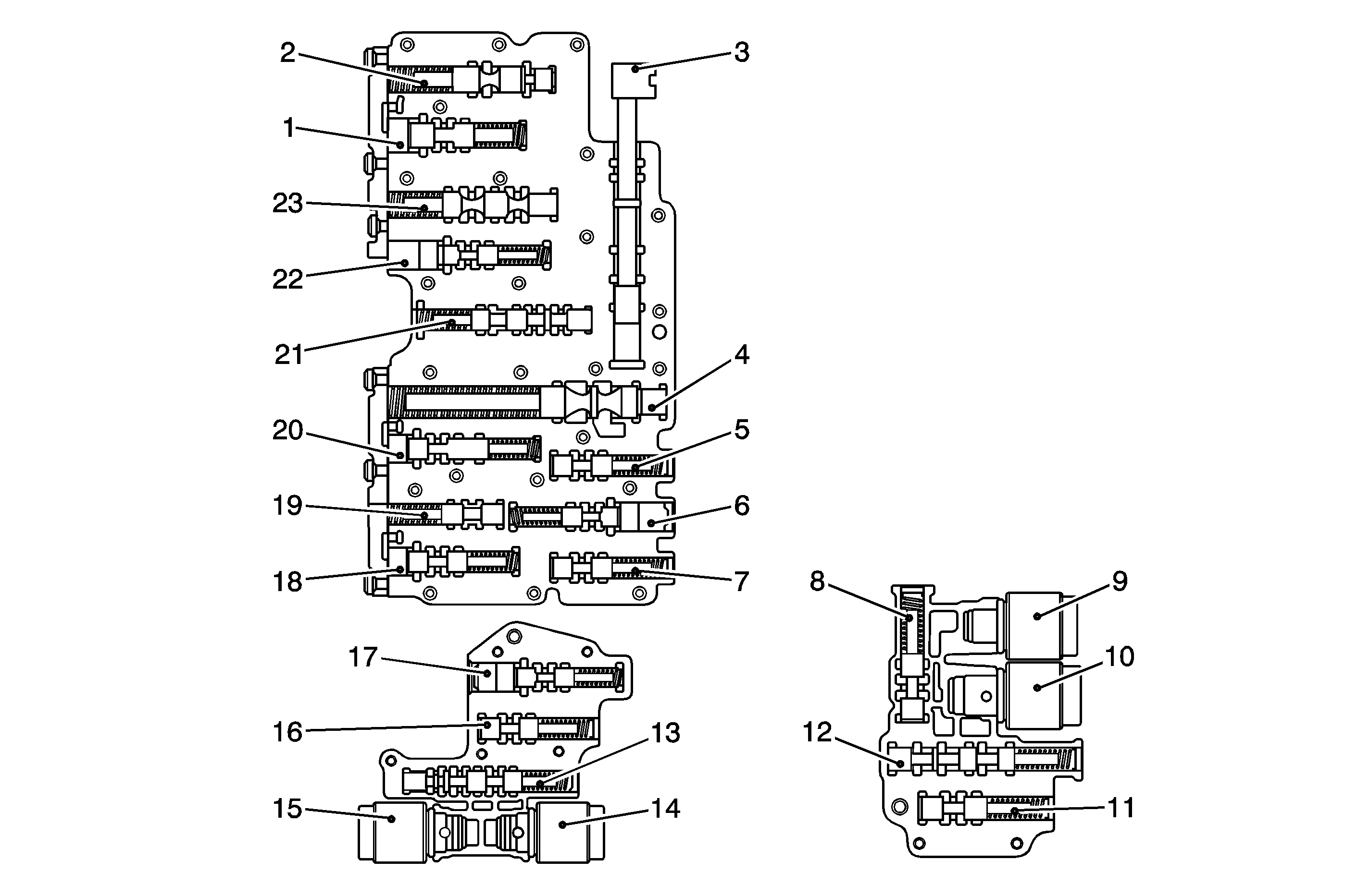
Torque Converter
The converter consists of the following components:
| • | The impeller |
| • | The turbine wheel |
| • | The reaction member: stator |
| • | The oil to transmit torque |
The impeller, which is driven by the engine, causes the oil in the converter to flow in a circular pattern. This oil flow meets the turbine wheel, which deflects the direction of flow. At the hub the oil leaves the turbine and reaches the reactor member, or stator, which again deflects the oil so that the oil reaches the impeller at the correct angle of flow.
The reversal effect generates movement in the stator. The reaction torque then amplifies the turbine torque.
The ratio between the turbine torque and the torque is called torque multiplication.
The greater the difference in speed between the pump and the turbine, the greater the torque multiplication. The turbine is at a standstill when the torque multiplication is highest. The higher the speed of the turbine, the lower the torque multiplication.
When the turbine speed reaches about 85 percent of the pump speed, torque multiplication is equal to 1, that is, the turbine torque is equivalent to pump torque.
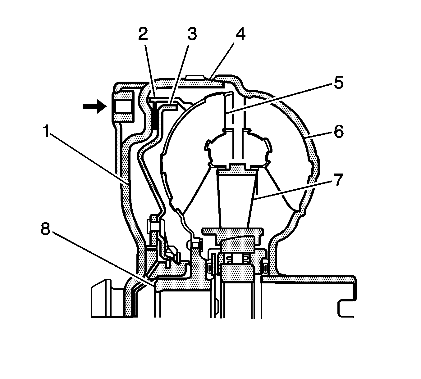
The stator, which bears against the housing via the freewheel, is then rotating freely in the oil flow, and the freewheel is overcome. From this point onwards, the converter acts as a straightforward fluid coupling.
The illustration identifies the following components in the space behind the lock-up clutch piston:
- Friction Lining
- Lock-up Clutch Piston
- Converter Cover
- Turbine Wheel
- Impeller
- Stator
- Turbine Hub
- Torque Converter Impeller Hub
Torque Converter Lock-up Clutch (TCC)
The TCC is a device which eliminates converter slip which helps to improve fuel consumption.
The TCC is engaged and released in a controlled manner. During the controlled phase, a slight speed difference between the impeller and the turbine wheel is established. This ensures that the engine's rotating vibration is not phased on to the transaxle. The result is optimum shift quality.
An electronic pressure-regulating valve determines pressure regulation of the TCC piston.
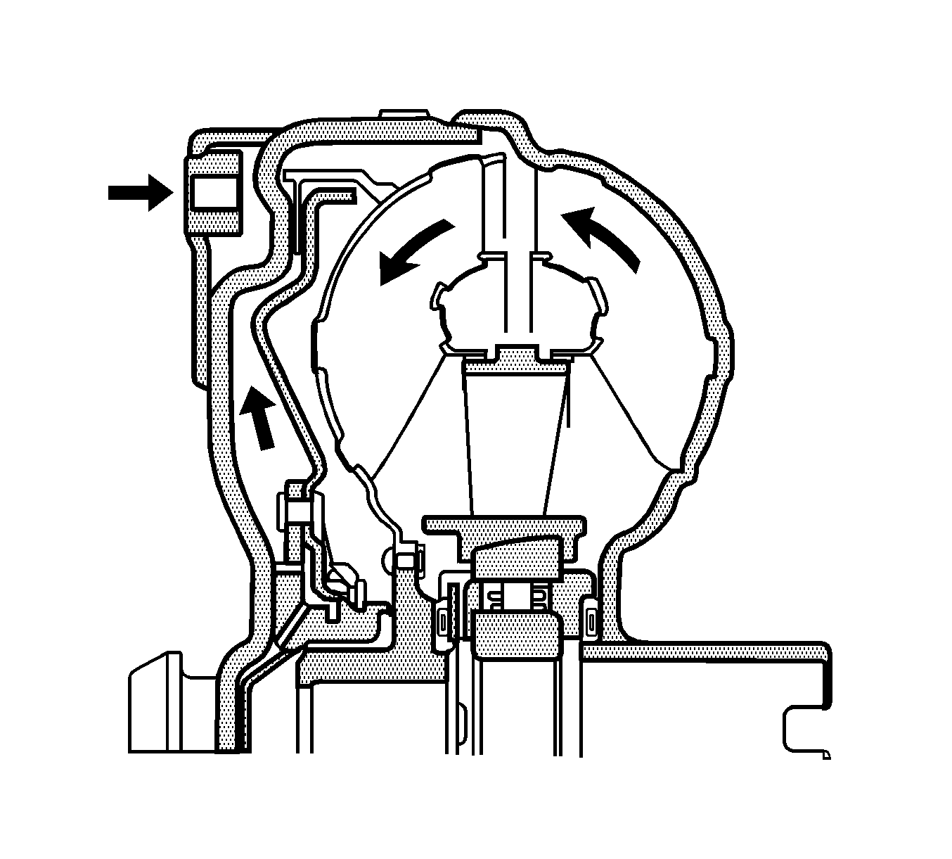
When the piston is open, the oil pressure behind the TCC piston is equal to the pressure in the turbine zone. The direction of flow is through the turbine shaft and through the space behind the piston to the turbine chamber.
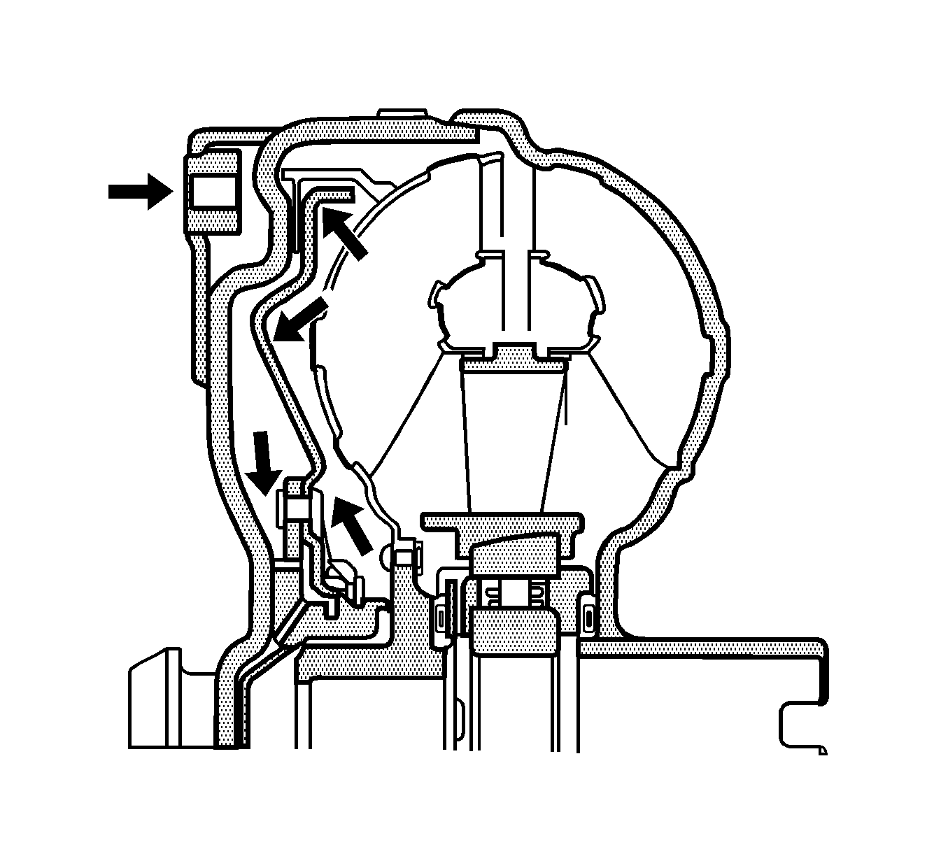
The direction of flow is reversed through a valve in the hydraulic selector unit, engaging the TCC. At the same time the space behind the TCC piston is vented. The oil pressure passes from the turbine chamber to the TC piston and presses the piston against the converter cover. The turbine is thus blocked by way of the linings between the piston and the cover, permitting rigid through drive with no slip or reduced slip to the mechanical stage of the transaxle.
Fluid Pump
The fluid pump is located between the torque converter and the transaxle case and is driven directly by the torque converter. The pump sucks the fluid through a filter and delivers the fluid to the main pressure regulator valve of the control system. Excess fluid flows back to the pump. The fluid pump fulfills the following functions:
| • | Generates line pressure |
| • | Delivers fluid under pressure to the torque converter, preventing air bubbles in the fluid |
| • | Induces a flow of fluid through the torque converter in order to eliminate heat. |
| • | Supplies fluid pressure to the hydraulic control system |
| • | Supplies fluid pressure to the shift components |
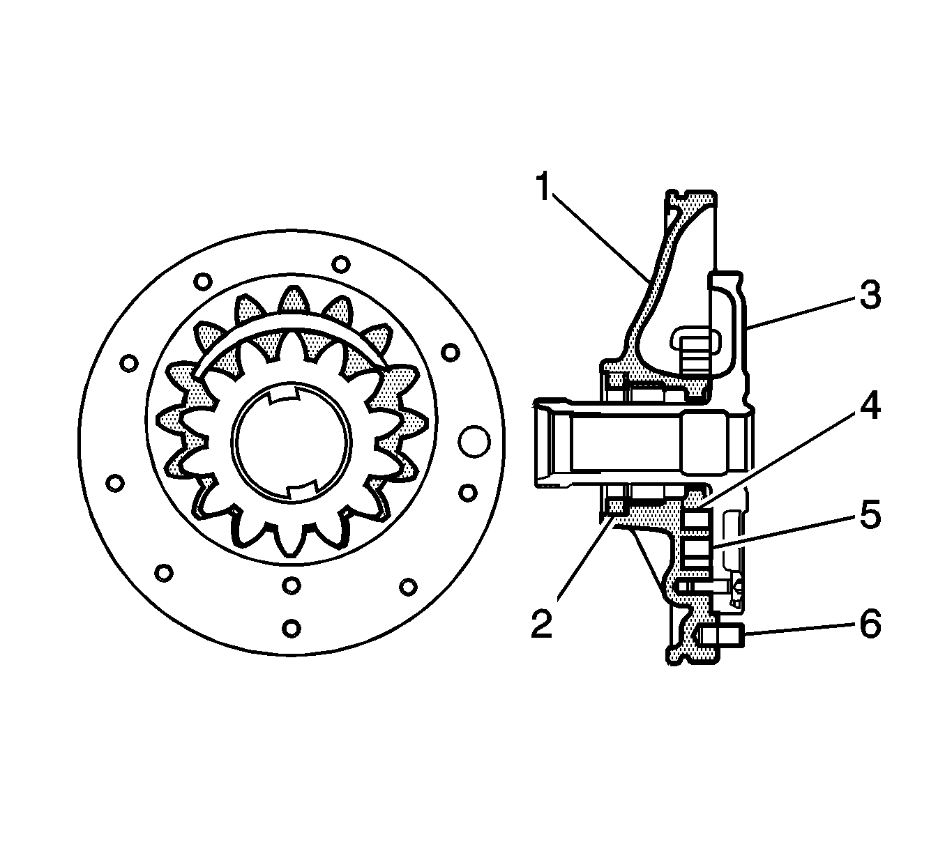
The illustration identifies the following components within the pump housing:
- Disc
- Shaft Seal
- Stator Shaft
- Pump Wheel
- Pump Ring Gear
- Dowel Pin
Planetary Gears
The ZF 4HP 16 automatic transaxle is equipped with the following gears:
| • | 1 sun gear |
| • | 4 planetary gears |
| • | A planetary carrier |
| • | A ring gear |
Each gear is located one directly behind the other and are linked together, so that the front ring gear is permanently linked to the rear planet carrier and the front planetary carrier is linked to the rear ring gear.
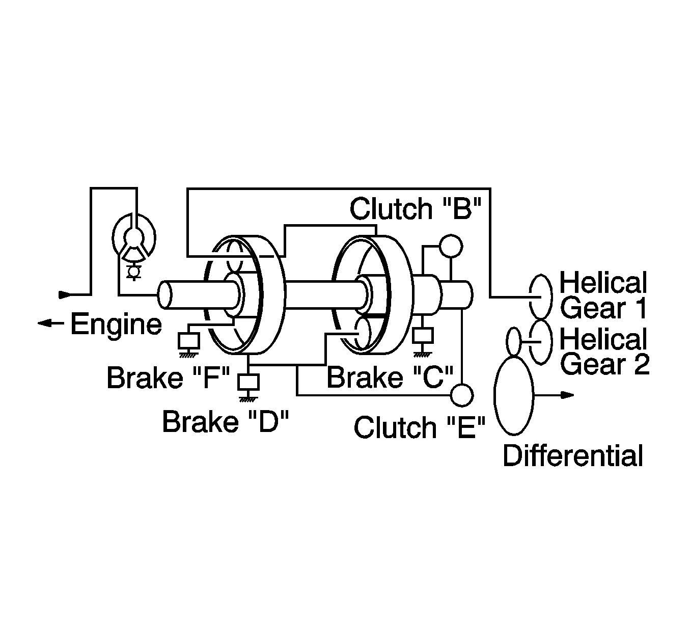
The individual gear ratios are obtained by linking together the gear set elements in different ways by means of clutches and brakes.
On the 4HP 16, the power flow is directed into the planetary gear set through the rear planetary carrier or the rear sun gear, or through both simultaneously, depending on the gear. The output is always through the front planetary carrier.
Shift Elements: Multi-disc Clutches and Brakes
The shift elements perform shifts under load without interrupting the tractive flow. The illustration identifies the following components:
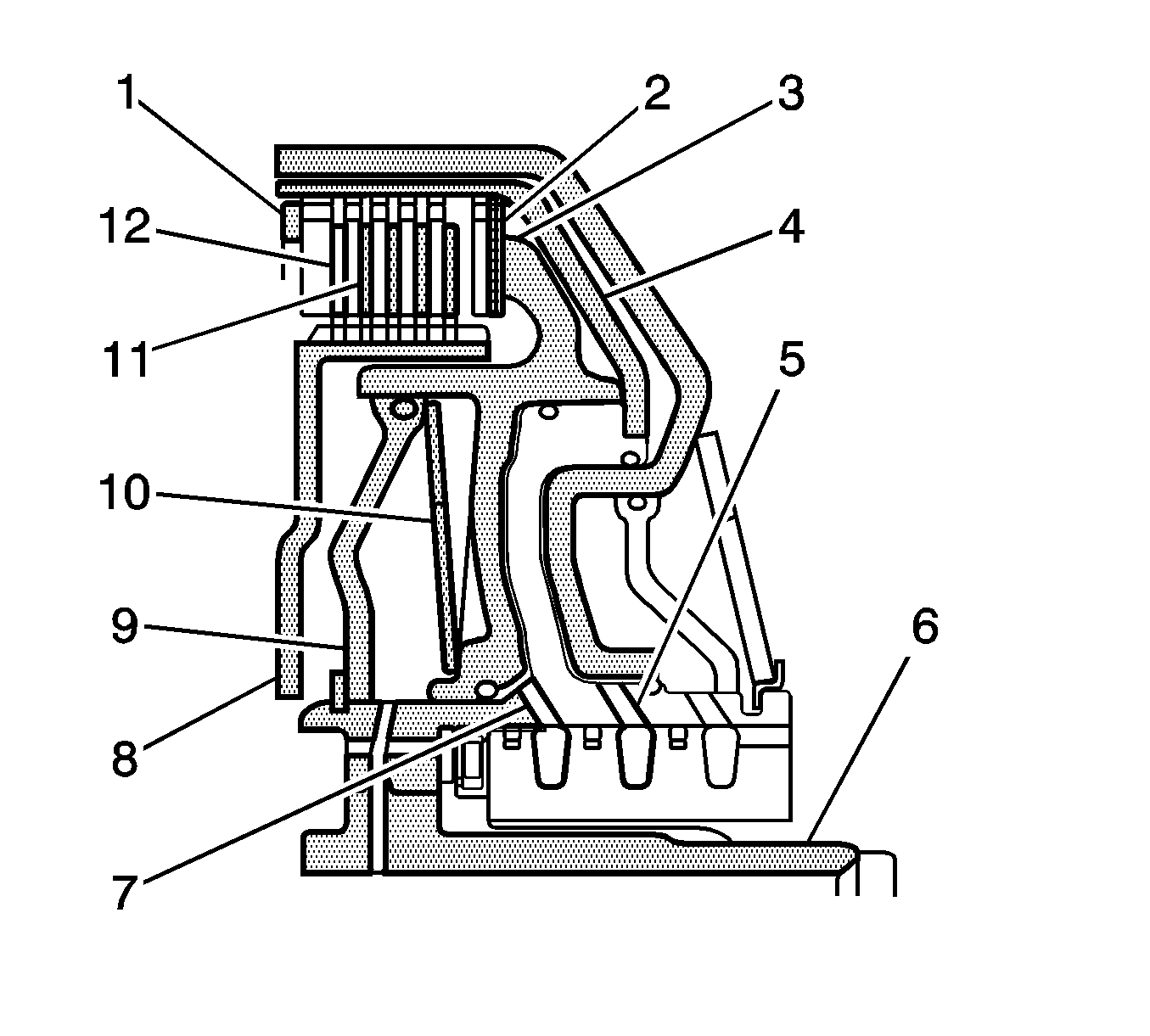
- Snap Ring
- Steel Disc
- Lined Disc
- Cup Spring
- Oil Supply to Dynamic Pressure Equalizer
- Baffle Plate
- Disc Carrier
- Oil Supply to Clutch
- Input Shaft
- Cylinder
- Piston
- Spring Disc
The shift elements are engaged hydraulically. The pressurized oil reaches the space between the cylinder and the piston, which compresses the discs. The clutch/brake is engaged when the oil pressure drops and the cup spring acts on the piston, pressing the piston back into the initial position. This releases the clutch/brake again.
Depending on the gear, the multi-disc clutches B and E supply the engine torque to the planetary gear train. The multi-disc brakes C, D, and F direct the torque into the housing.
The dynamic pressure at clutch B is equal to the pressure at clutch E, that is, the dynamic pressure in front of the piston equals the pressure behind the piston. This equalizing effect occurs in the following way:
- The space between the baffle plate and the piston is filled with unpressurized oil.
- A dynamic pressure dependent on the engine speed builds up.
- The space between pressure also builds up.
- Simultaneously a static pressure occurs, which causes the clutch to engage.
- If the static pressure is relieved, the cup spring is able to force the piston back into the original position.
The advantages of this dynamic pressure equalization are reliable clutch openings in all speed ranges, and smoother shifts.
Parking Lock
The parking lock is actuated by the selector lever when the gear is in Park. The lock protects the vehicle mechanically against rolling away.
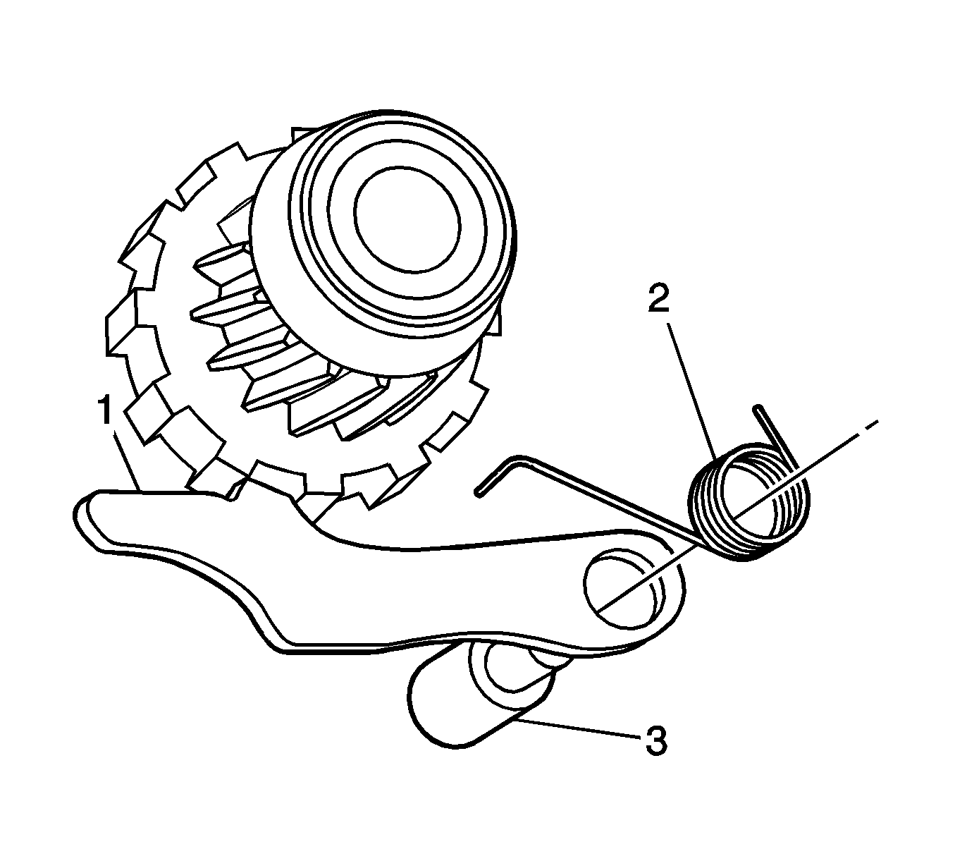
The stop plate is actuated by the selector shaft, which is permanently connected to the selector lever by a pull cable. The parking lock pawl (1) on the parking lock gear is welded onto the lateral shaft of the transaxle and this prevents the drive wheels from turning.
- Pawl
- Leg Spring
- Supporting Bolt
Valve Body
The valve body performs the following tasks:
| • | Generates the line pressure needed for actuating the shift elements |
| • | Actuates the individual shift elements by way of the clutch valves |
| • | Assures limited operation of the automatic transaxle in the event of the electronics failing |
| • | Actuates the lock-up clutch |
| • | Generates the lubricating pressure for the transaxle |
