For 1990-2009 cars only
Removal Procedure
- Raise and support the vehicle. Refer to Lifting and Jacking the Vehicle.
- Remove the rear tire and wheel assembly. Refer to Tire and Wheel Removal and Installation.
- For vehicles equipped with the antilock braking system (ABS), disconnect the rear wheel speed sensor electrical connector and remove the ABS harness from the lower control front arm.
- Use paint in order to mark the position of the adjuster cam relative to the control arm and the rear crossmember.
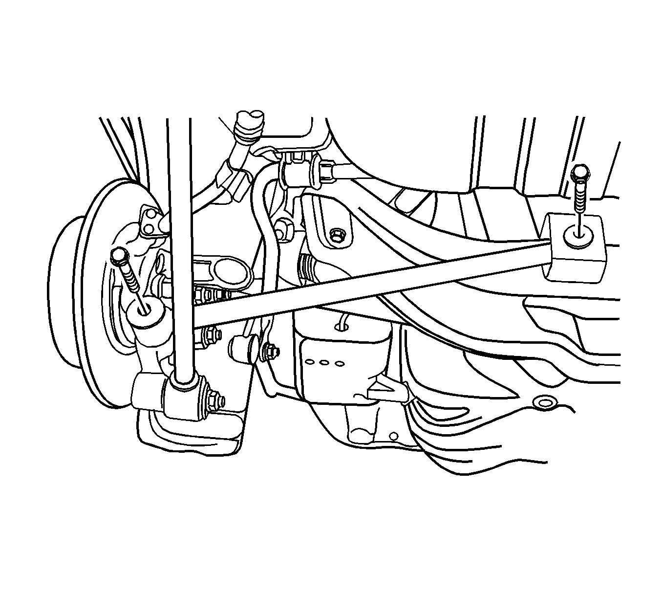
- Remove the lower control front arm bolt from the rear crossmember.
- Remove the lower control front arm bolt from the rear knuckle.
- Remove the lower control front arm from the vehicle.

Installation Procedure
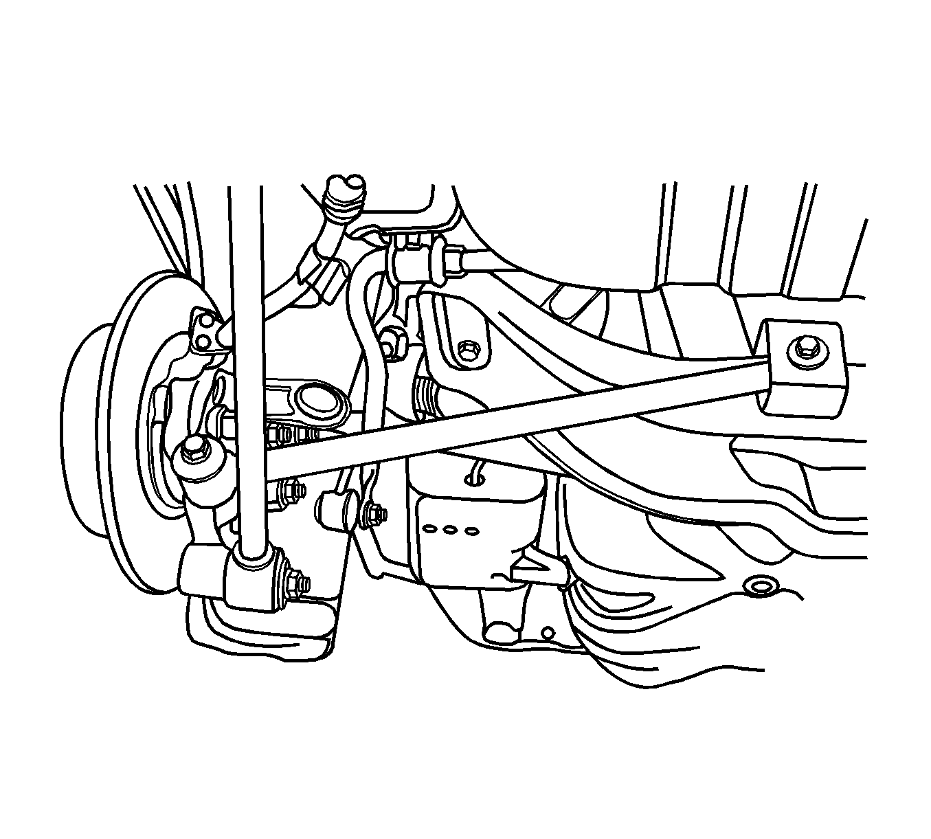
- Install the lower control front arm onto the rear knuckle with the bolt.
- Install the lower control front arm onto the rear crossmember with the bolt.
- Align the match marks on the adjuster cam in order to maintain the rear toe.
- For vehicles equipped with ABS, install the ABS harness onto the lower control front arm and connect the rear wheel speed sensor electrical connector.
- Install the rear tire and wheel assembly. Refer to Tire and Wheel Removal and Installation.
- Perform a rear toe adjustment and tighten the lower control front arm-to-rear crossmember bolt. Refer to Rear Toe Adjustment.
- Lower the vehicle.
Notice: Refer to Fastener Notice in the Preface section.

Tighten
Tighten the lower control front arm-to-knuckle bolt to 120 N·m (89 lb ft).
Important: Do not tighten the lower control front arm-to-rear crossmember bolt yet. Tightening the bolt is part of the rear toe adjustment procedure.
