Removal Procedure
Caution: Refer to Battery Disconnect Caution in the Preface section.

- Disconnect the negative battery cable.
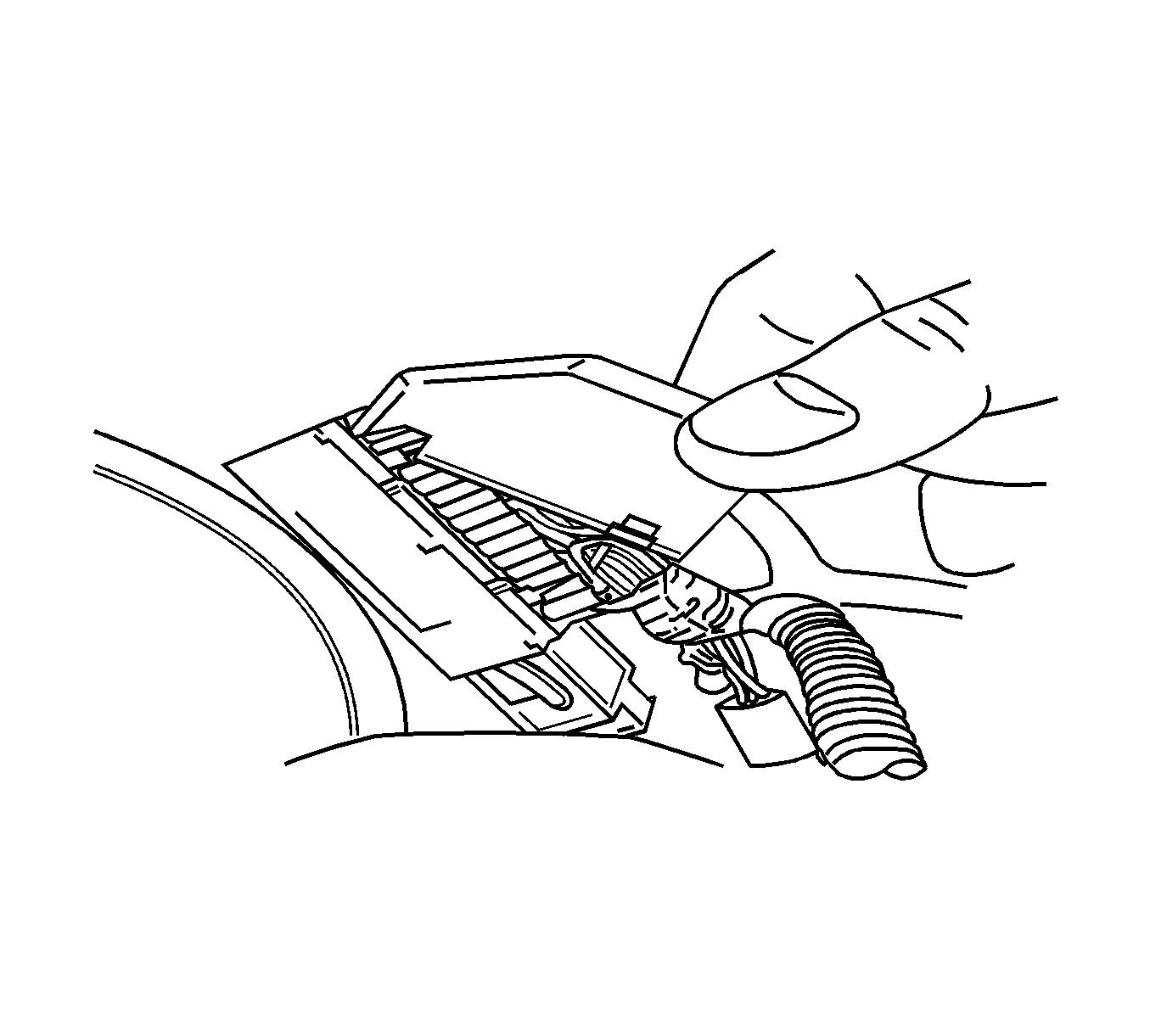
- Disconnect connector from the electronic brake control module (EBCM).
- Remove the appropriate terminals from connector:
| • | Right-side--terminals 4, WH, and 5, GY |
| • | Left-side--terminals 6, BN, and 7, L-BU |

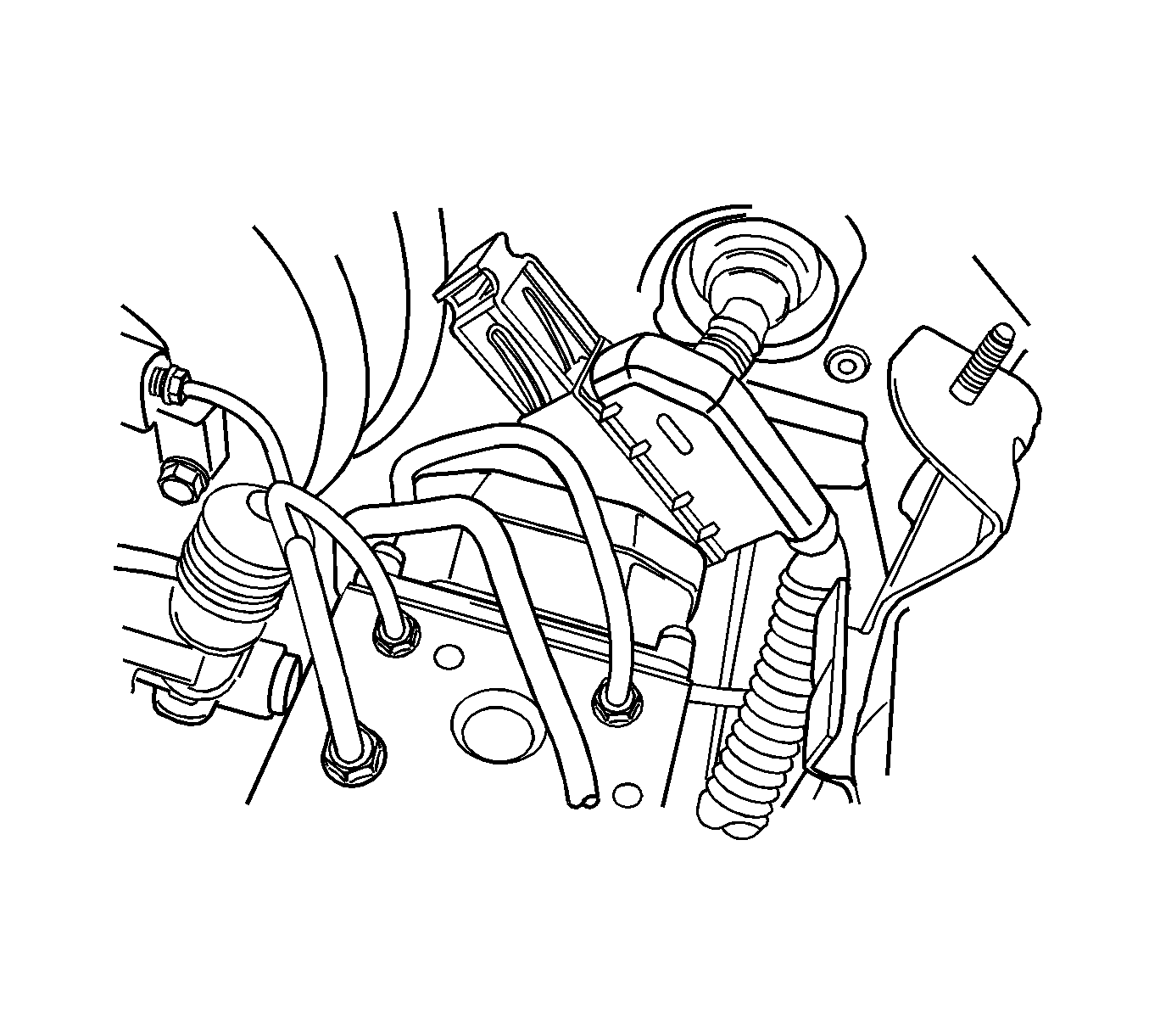
- Both speed sensor harnesses break out of the antilock brake system (ABS) wiring harness just beyond the ABS connector. The right-side speed sensor harness
crosses the top of the fire wall to the right-side fender area. The left-side speed sensor harness goes directly to the left-side fender area.
- Free the speed sensor harness from the wiring harness.
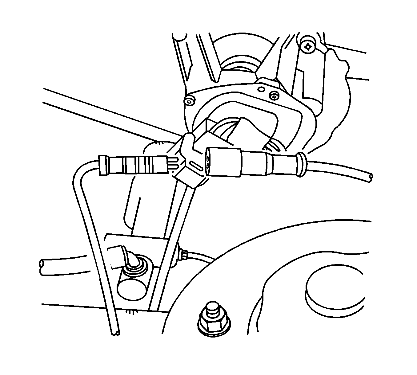
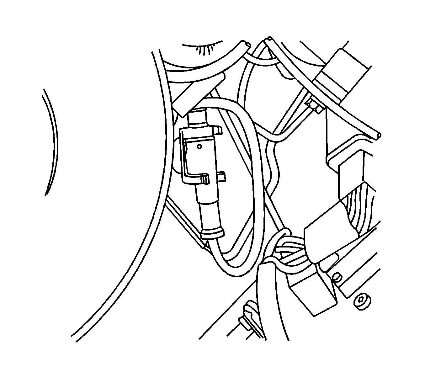
- Remove the front wheel speed sensor electrical connector from the retaining clamps and disconnect the harness from the sensor connector.
Installation Procedure

- Install the front wheel speed sensor jumper harness.
- Connect the front wheel speed sensor electrical connector and secure it into the clamps.

- Replace the jumper harness into the wiring harness.
- Insert the terminals into connector as they had been removed:
| • | Right-side--terminals 4, WH, and 5, GY |
| • | Left-side--terminals 6, BN, and 7, L-BU |
- Connect EBCM connector.
- Connect the negative battery cable.


