Special Tools
CH-47717 Fuel Lock Ring Remover Tool
Removal Procedure
Warning: Gasoline or gasoline vapors are highly flammable. A fire could occur if an ignition source is present. Never drain or store gasoline or diesel fuel in an open container, due to the possibility of fire or explosion. Have a dry chemical (Class B) fire extinguisher nearby.
Warning: Provide proper ventilation when working with fuel in enclosed areas where fuel vapors can collect. The lack of adequate ventilation may result in personal injury.
Warning: Always wear safety goggles when working with fuel in order to protect the eyes from fuel splash.
Warning: Remove the rear compartment floor trim to provide technician contact with the vehicle's metal surfaces. Failure to remove the rear compartment floor trim may cause a static electricity discharge to ignite any fuel vapor resulting in personal injury and vehicle damage.
Warning: Fuel Vapors can collect while servicing fuel system parts in enclosed areas such as a trunk. To reduce the risk of fire and increased exposure to vapors:
• Use forced air ventilation such as a fan set outside of the trunk. • Plug or cap any fuel system openings in order to reduce fuel vapor formation. • Clean up any spilled fuel immediately. • Avoid sparks and any source of ignition. • Use signs to alert others in the work area that fuel system work is in process.
Caution: Cap the fittings and plug the holes when servicing the fuel system in order to prevent dirt and other contaminants from entering the open pipes and passages.
Caution: Clean all of the following areas before performing any disconnections in order to avoid possible contamination in the system:
• The fuel pipe connections • The hose connections • The areas surrounding the connections
Note:
• Always replace the fuel sender assembly O-rings when reinstalling the fuel sender assembly. • Always maintain cleanliness when servicing fuel system components. • Do not bend the arm of the fuel gage float while removing the fuel sender assembly.
- Remove the fuel pump. Refer to Fuel Pump Replacement.
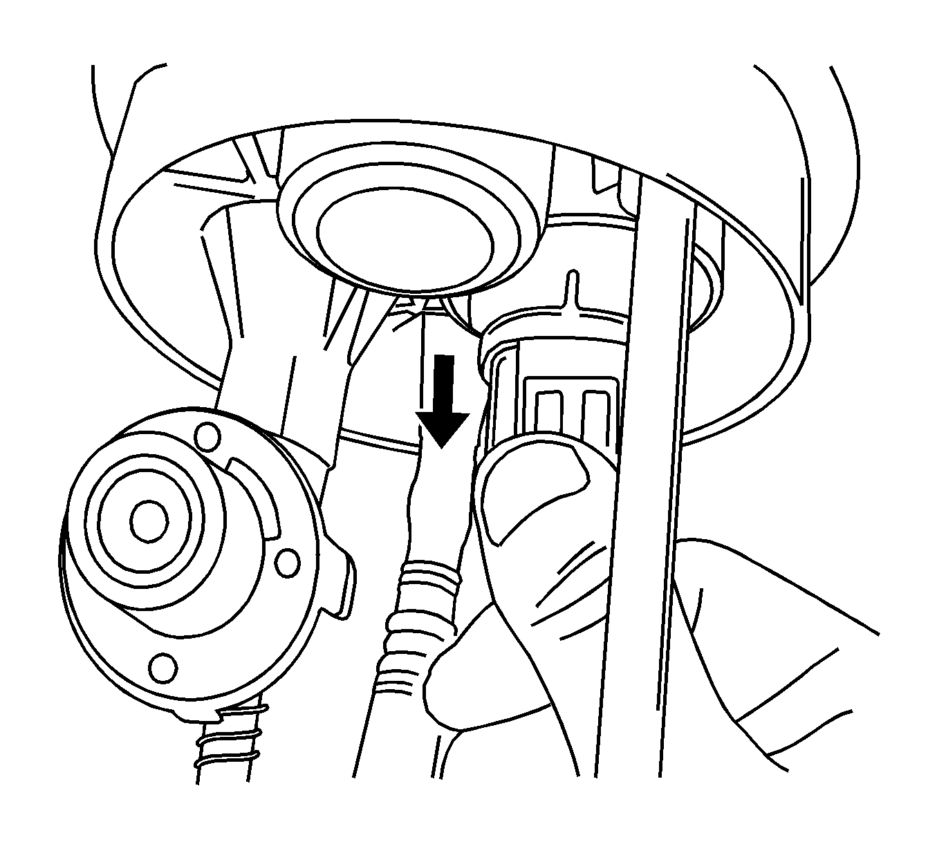
- Disconnect the fuel sender insulator connector.
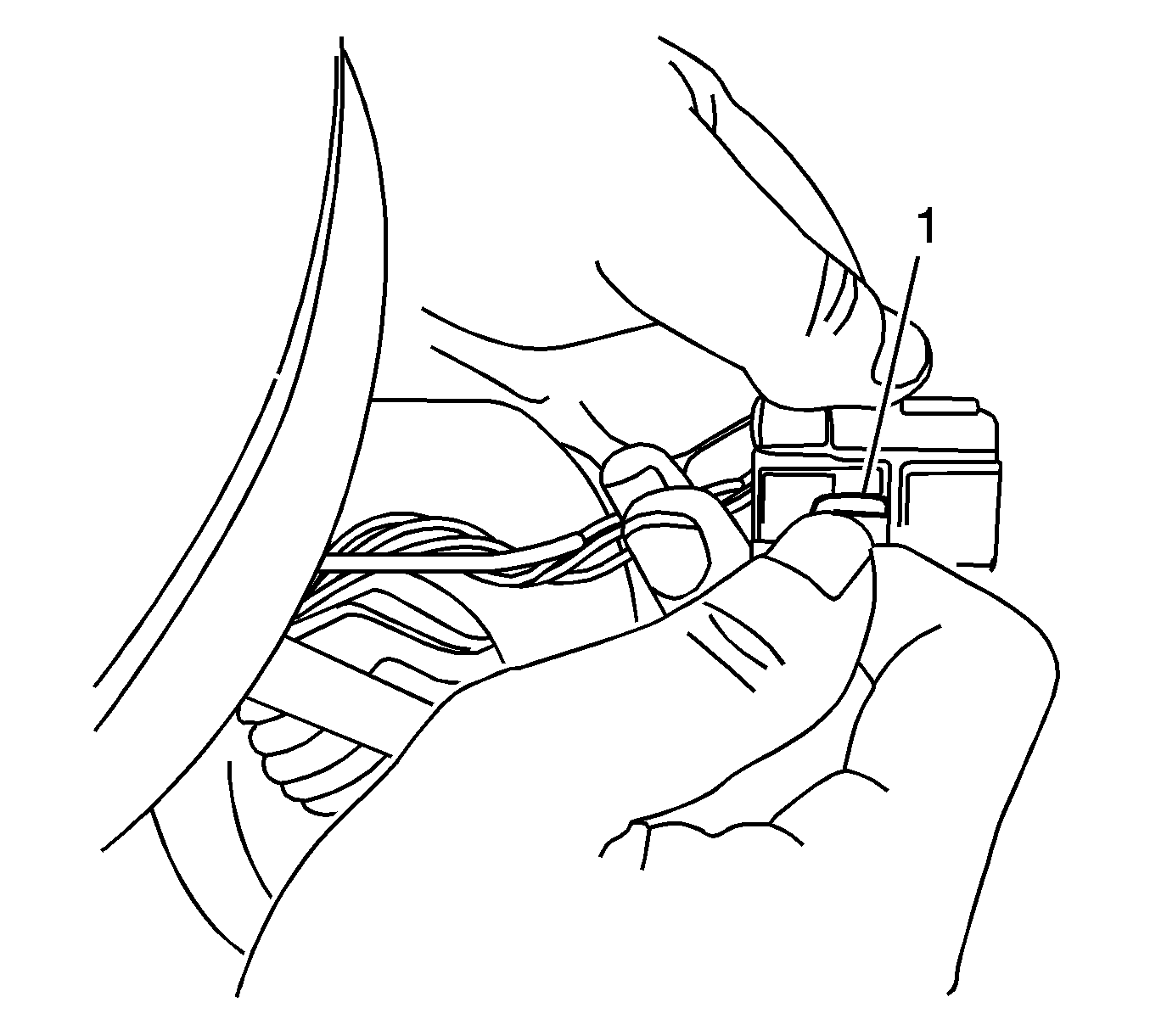
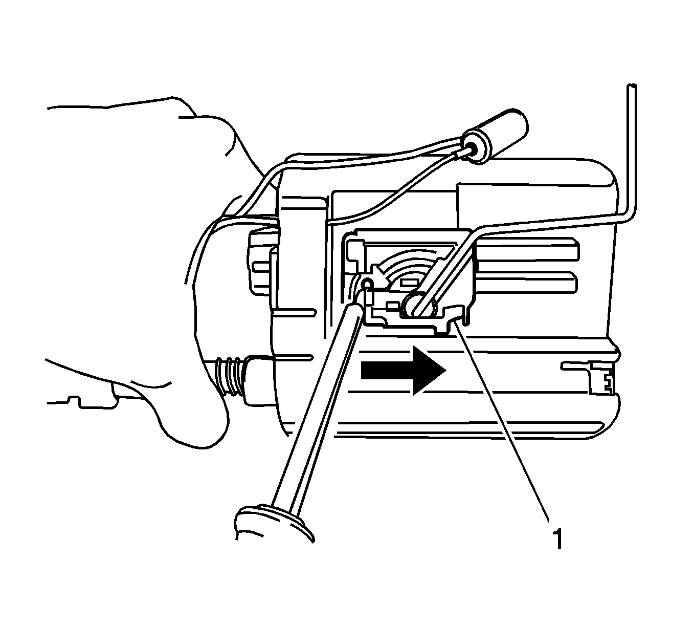
- To disconnect the fuel pump terminal, push the terminal wedge (1) in the insulator.
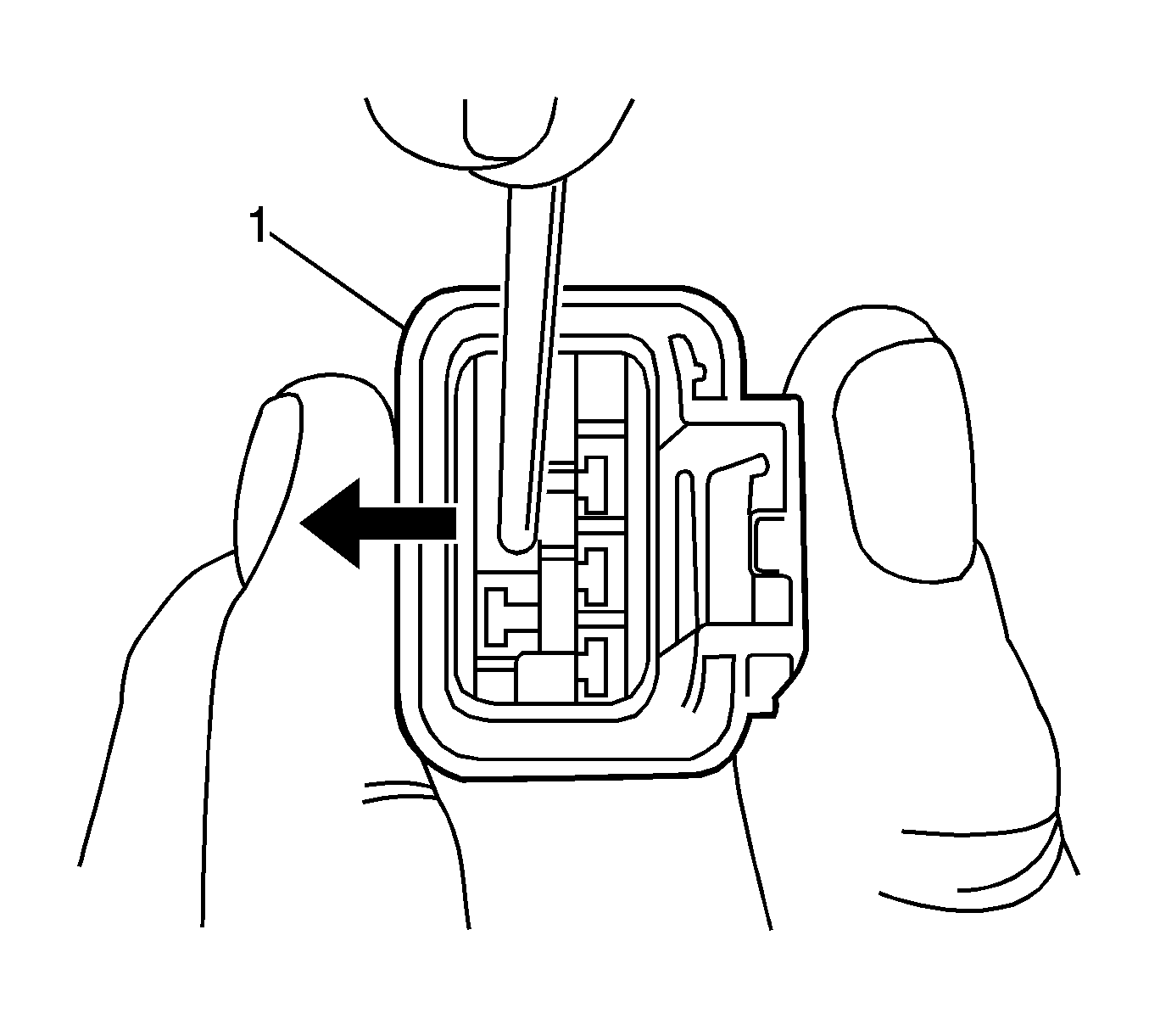
- Push the wedge (1) outside, then pull the wires to disconnect from the connector.
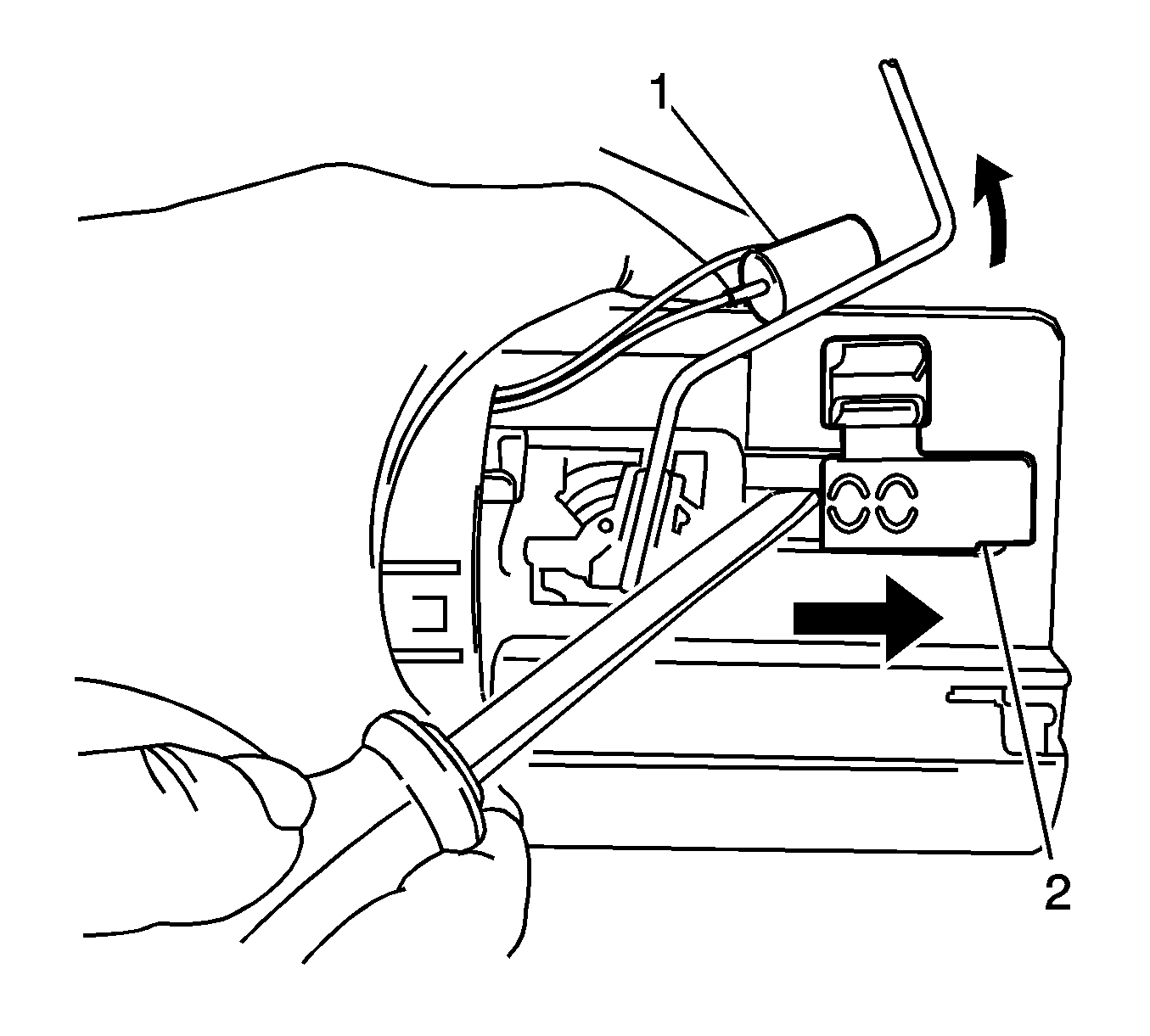
- Remove the fuel level sensor (1) from the sender housing, then remove the sender housing (2).
- Remove the fuel sender assembly (1).
Installation Procedure
Caution: Always re-attach the fuel lines and fuel filter with all original type fasteners and hardware.
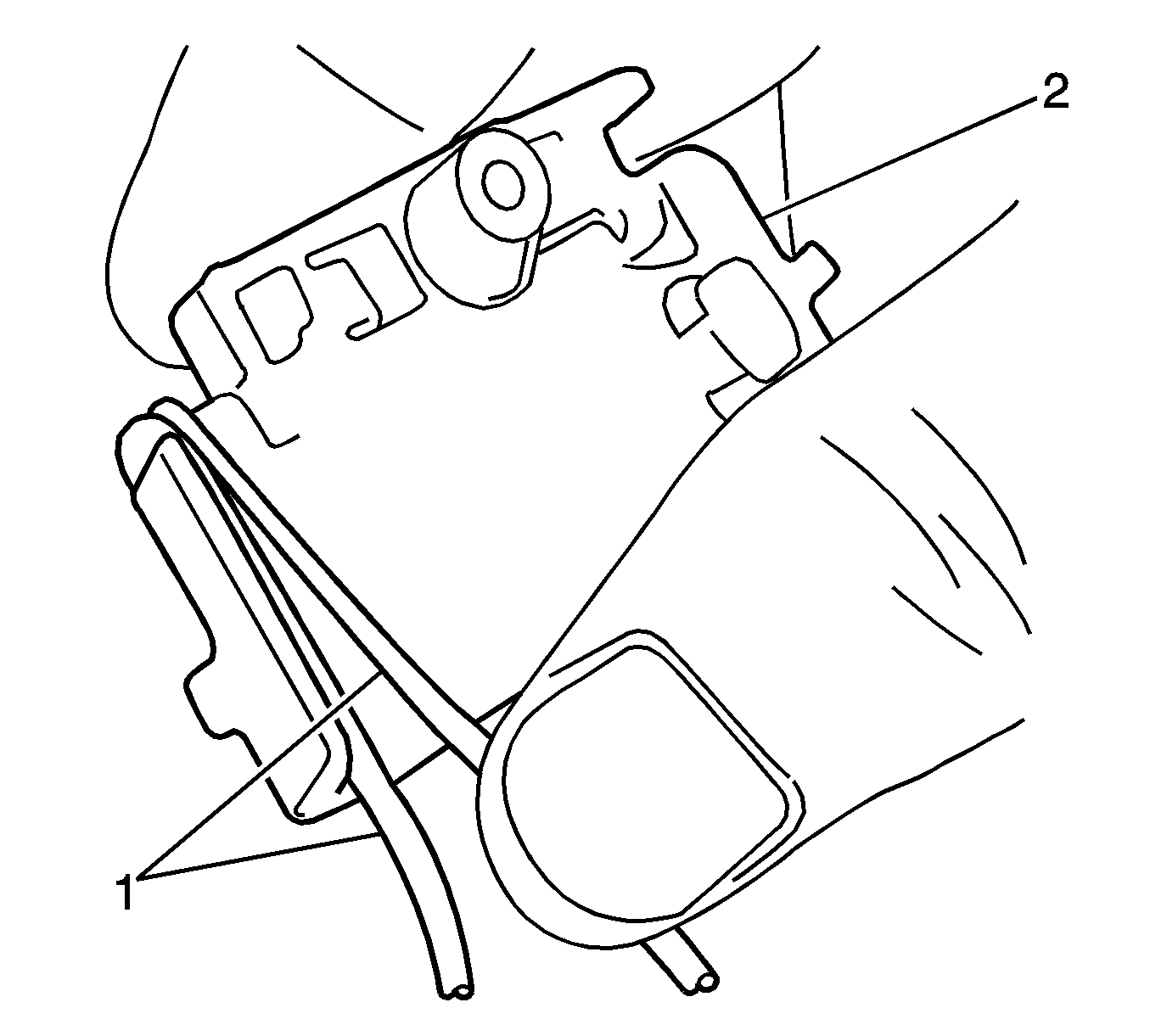
Do not repair sections of fuel pipes.- Wind the wires (1) around the sender assembly (2).
- Install the sender assembly onto the fuel pump assembly (1).
- Install the fuel level sensor onto the fuel sender housing.
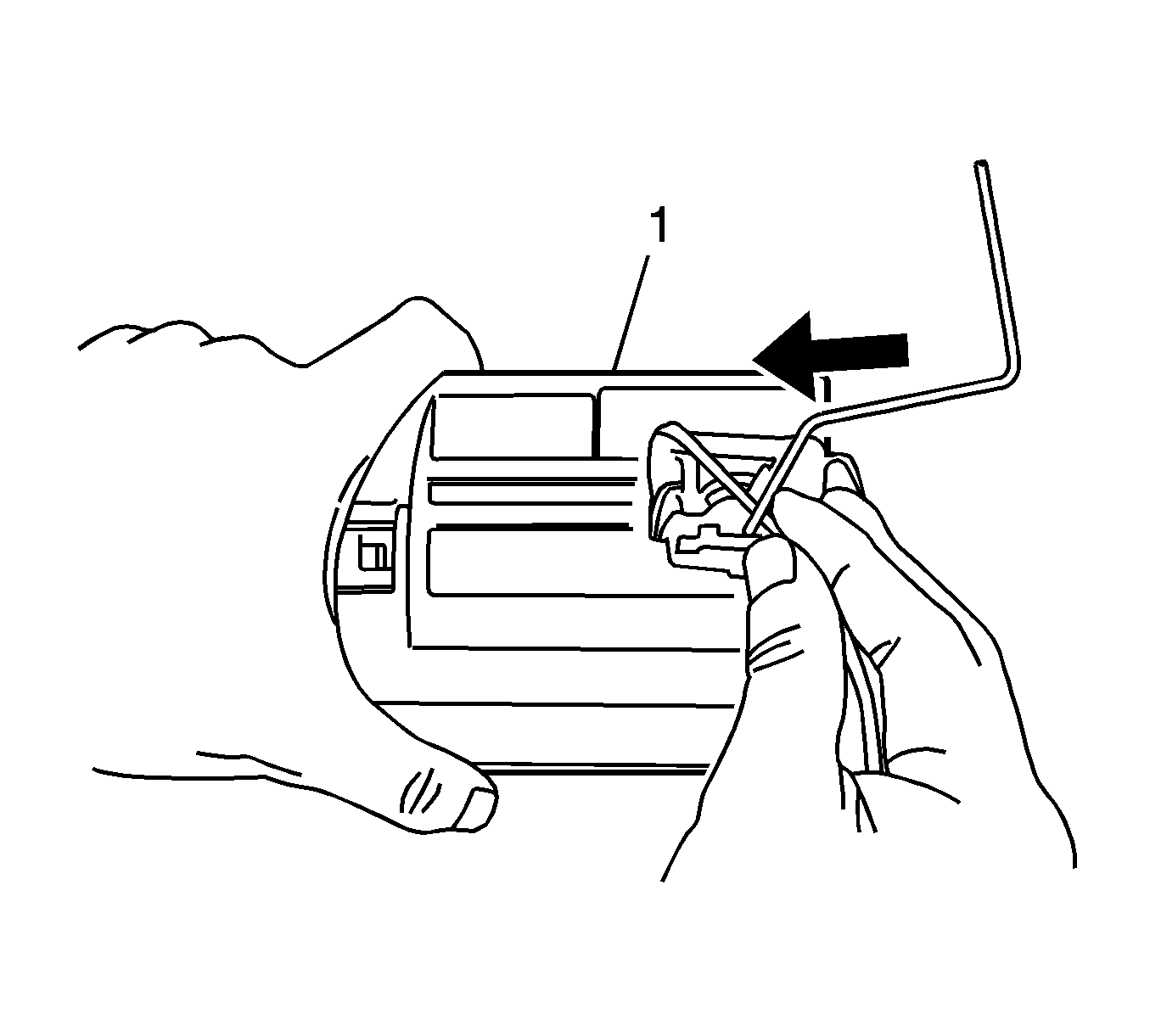
- Connect the wires into the insulator as follows:
- Connect the fuel sender insulator connector.
Note: Failure to install the fuel sender assembly correctly will result in fuel gauge inaccurate reading.
Note: Failure to install the fuel level sensor correctly will result in fuel level warning lamp inaccurate reading.
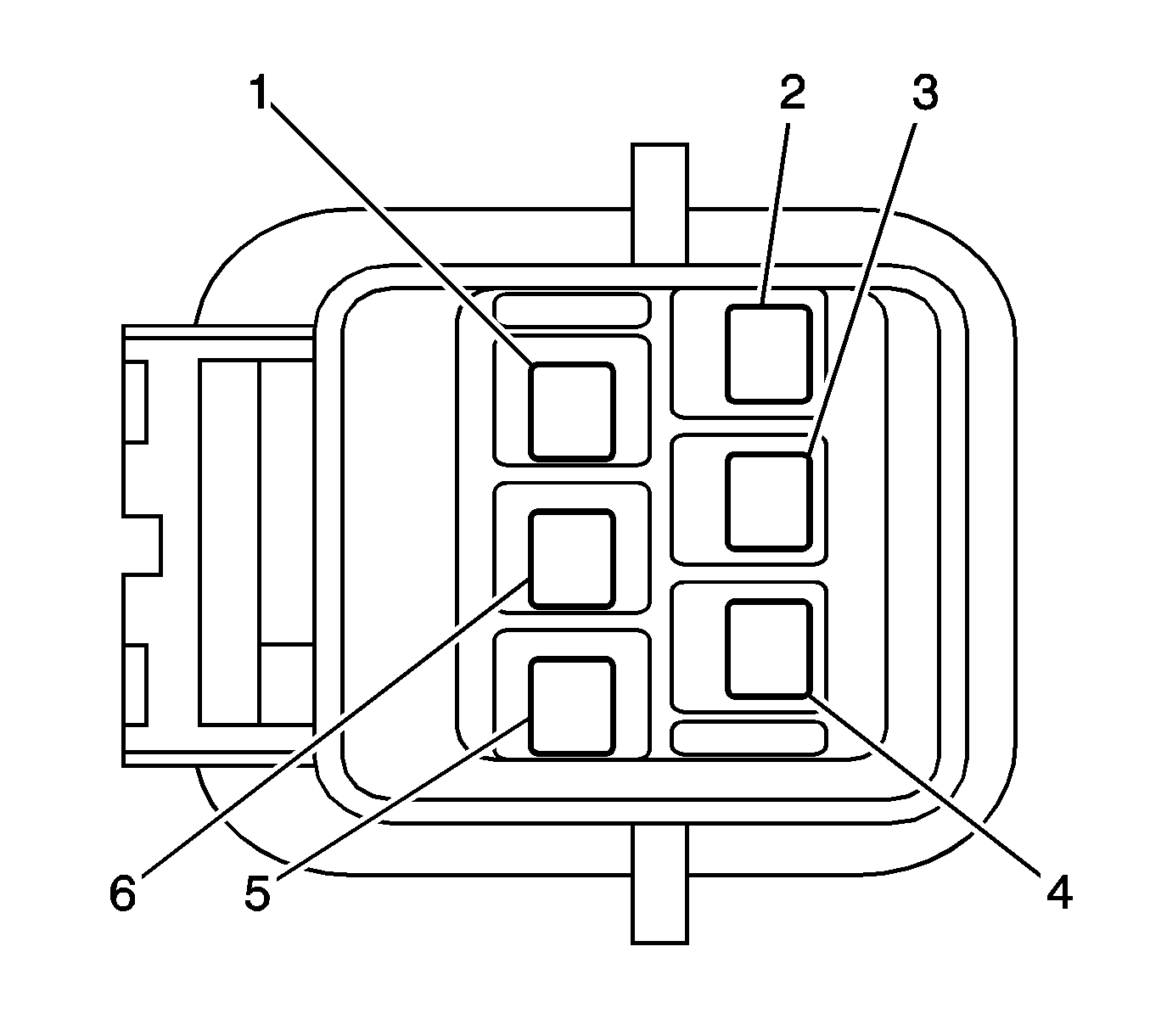
| • | Red (1) |
| • | Blue (2) |
| • | Gray (3) |
| • | Yellow (4) |
| • | Blue (5) |
| • | Black (6) |
| • | Install the fuel pump. Refer to Fuel Pump Replacement. |

