- Install the new spacer plate and gasket assembly (324) onto the rear control valve body assembly (326).
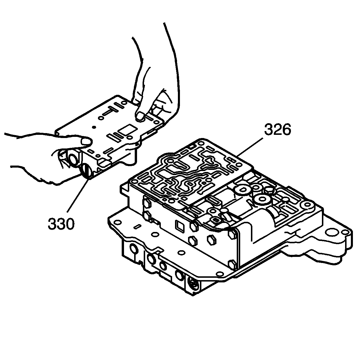
- Install the rear control valve body assembly (326) onto the middle control valve body assembly (323).
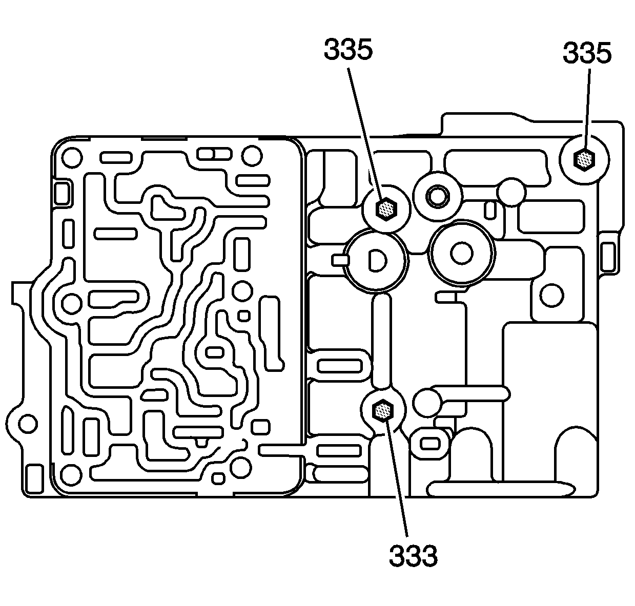
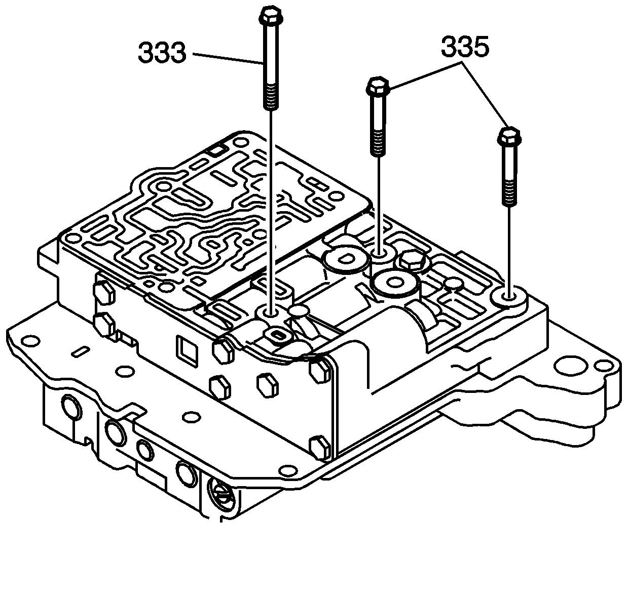
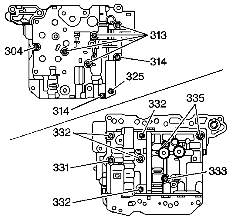
- Install 2 - M5 x 0.8 x 35 mm rear control valve body bolts (335).
- Install 1 - M5 x 0.8 x 40 mm rear control valve body bolt (333).
- Hand tighten the 3 rear control valve body assembly bolts (333, 335).
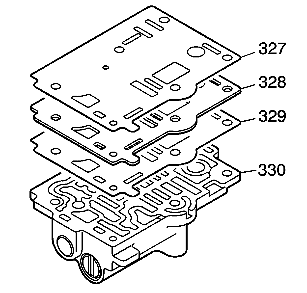
- Install the spacer plate (328) and the 2 new gaskets (327, 329) onto the No. 2 rear control valve body assembly (330).
- Install the No. 2 rear control valve body assembly (330) onto the rear control valve body assembly (326).
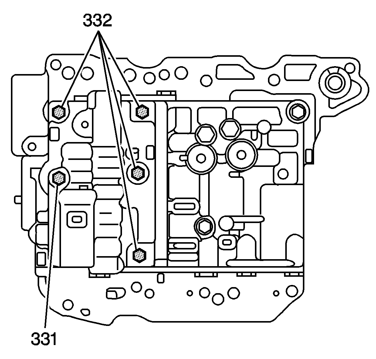
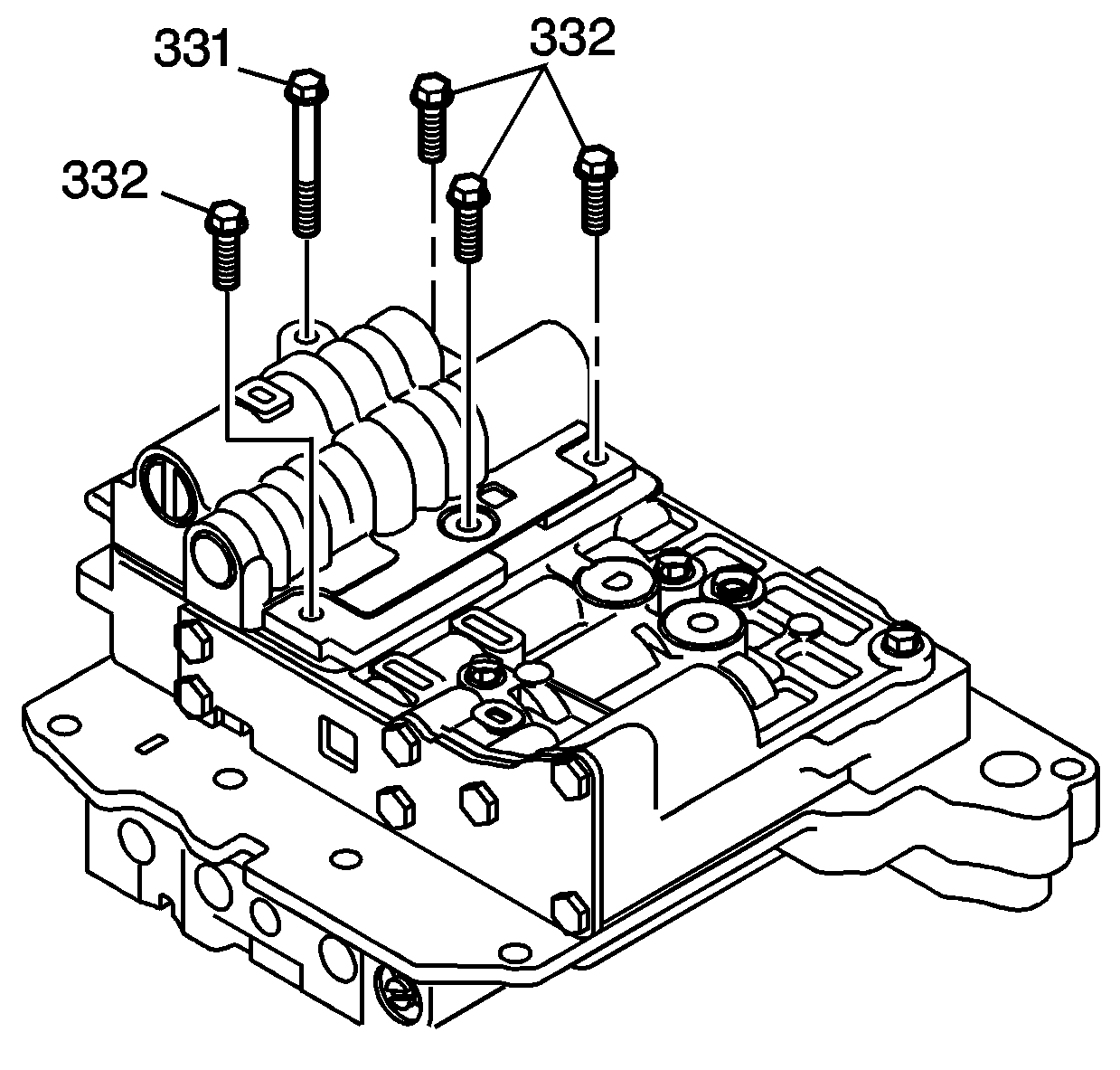
- Install 1 - M5 x 0.8 x 76 mm control valve body bolt (331) into the No. 2 rear control valve body assembly.
- Install 4 - M5 x 0.8 x 49.5 mm control valve body bolts (332) into the No. 2 rear control valve body assembly.
- Hand tighten the 5 control valve body assembly bolts (331, 332).
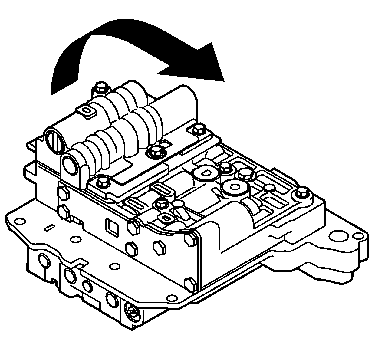
- Turn the valve body assembly over.
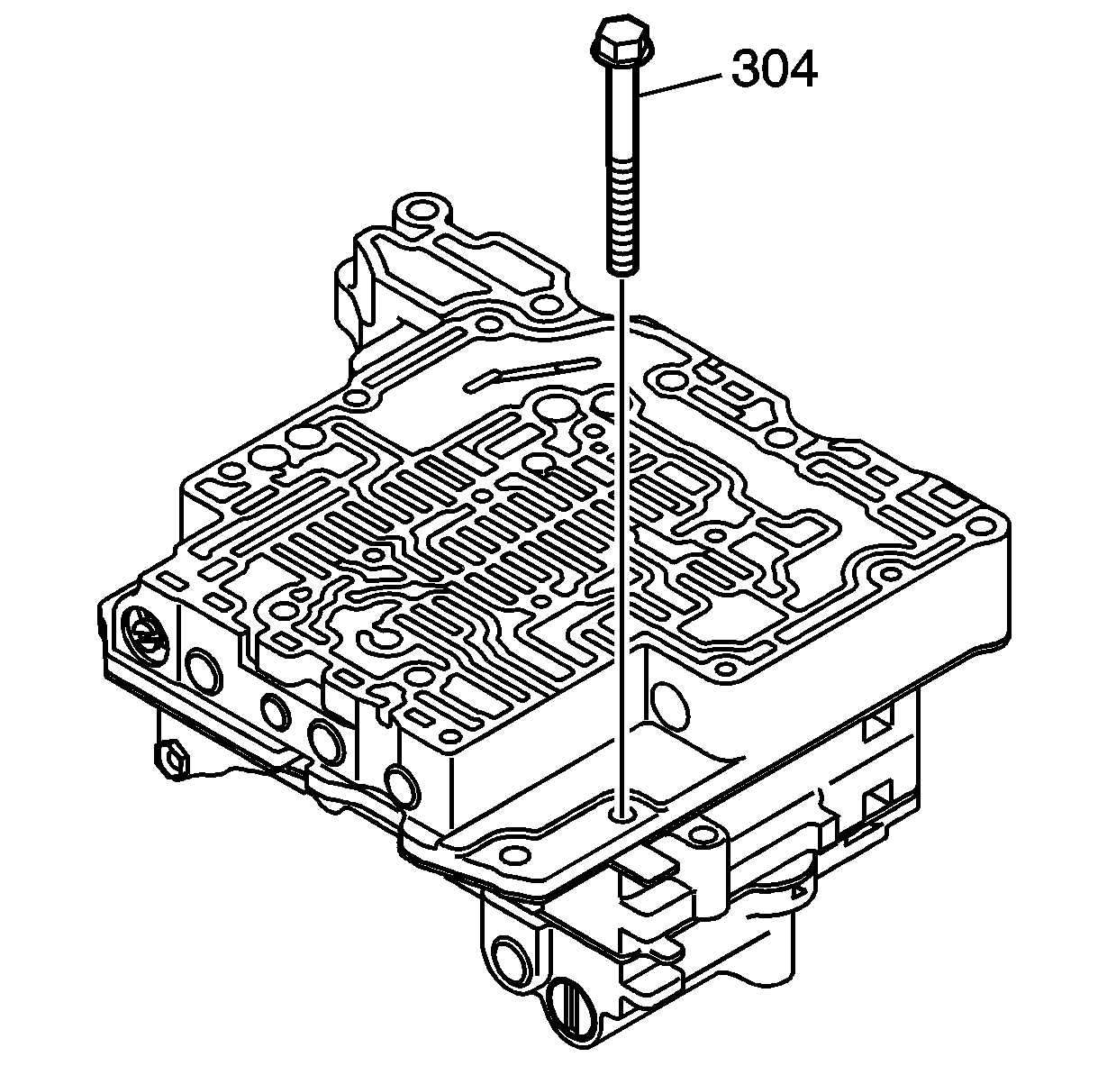
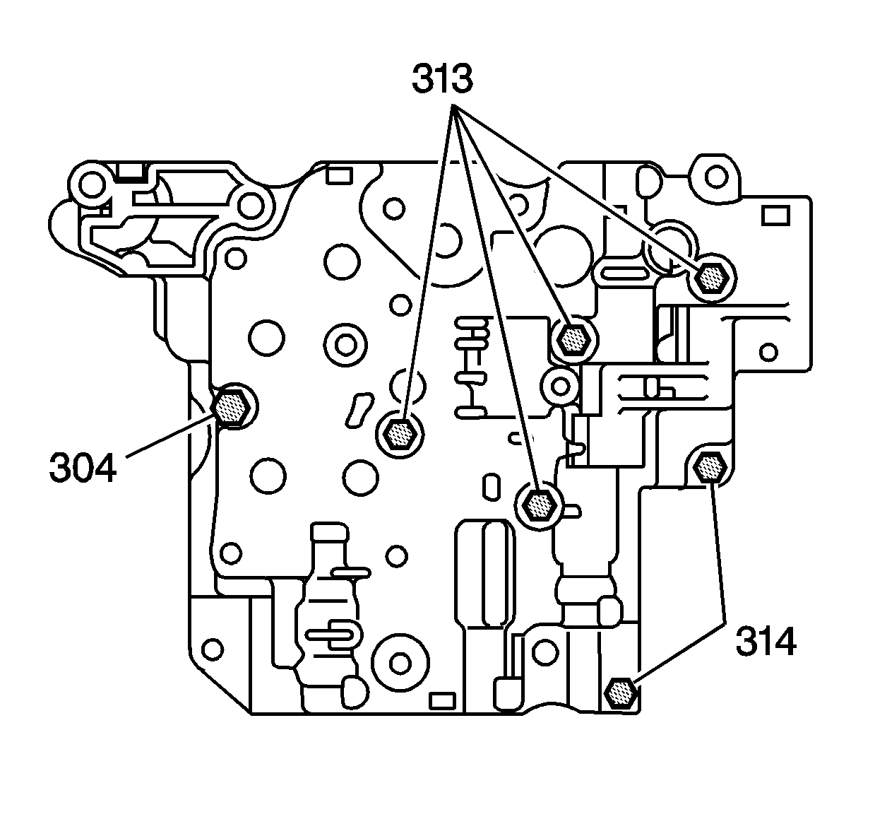
- Install the M5 x 0.8 x 50 mm control valve body bolt (304) and hand tighten.
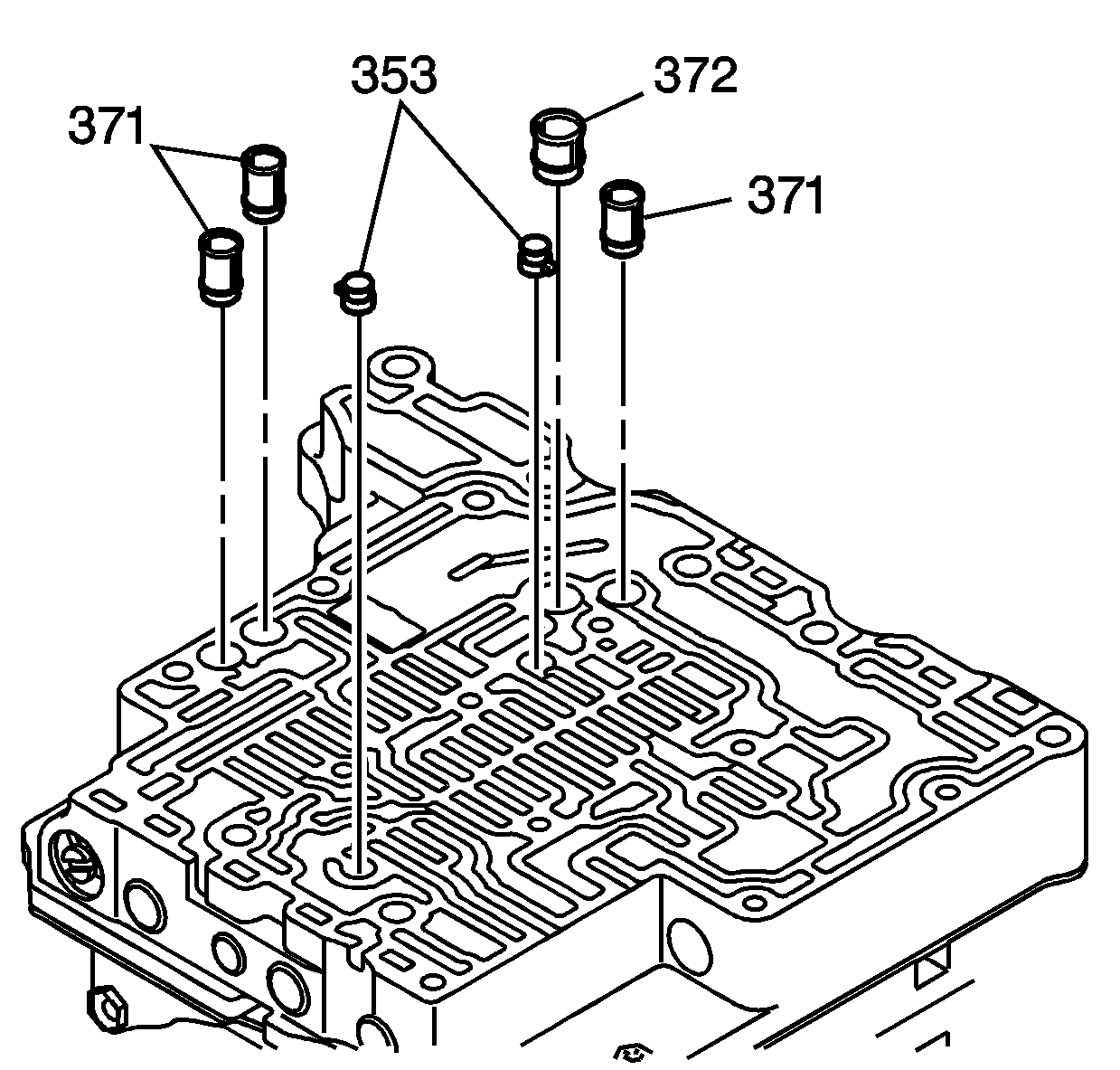
- Install the 3 fluid strainers (371), 1 fluid strainer (372), and the 2 accumulator check valve assemblies (353) into the middle control valve body assembly.
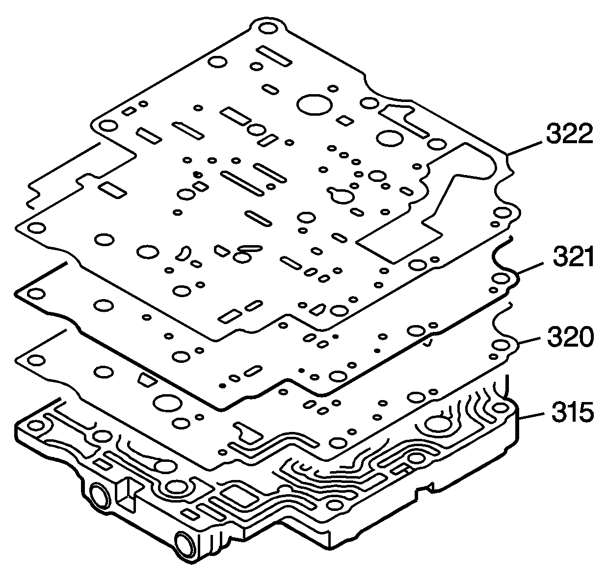
- Install the gasket (320) to the front control valve body assembly (315).
- Install the front control valve body spacer plate (321).
- Install the gasket (322).
- Install the spacer plate and gaskets on to the front control valve body assembly (315).
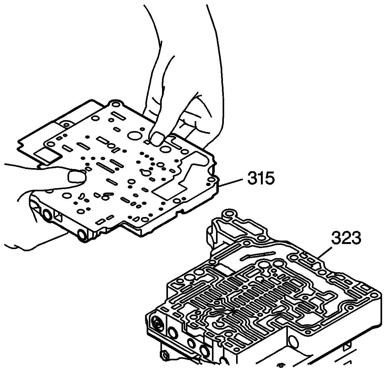
- Install the front control valve body assembly (315) onto the middle control valve body assembly (323).
- Install 1 - M5 x 0.8 x 50 mm control valve body bolt (304) into the front control valve body assembly and hand tighten.
- Install 4 or 5- M5 x 0.8 x 20 mm control valve body bolts (313) into the front control valve body assembly and hand tighten.
- Install 2 - M5 x 0.8 x 16 mm control valve body bolts (314) into the front control valve body assembly and hand tighten.
- Install all 16 control valve body assembly bolts, evenly and gradually and tighten to 7 N·m (62 lb in).
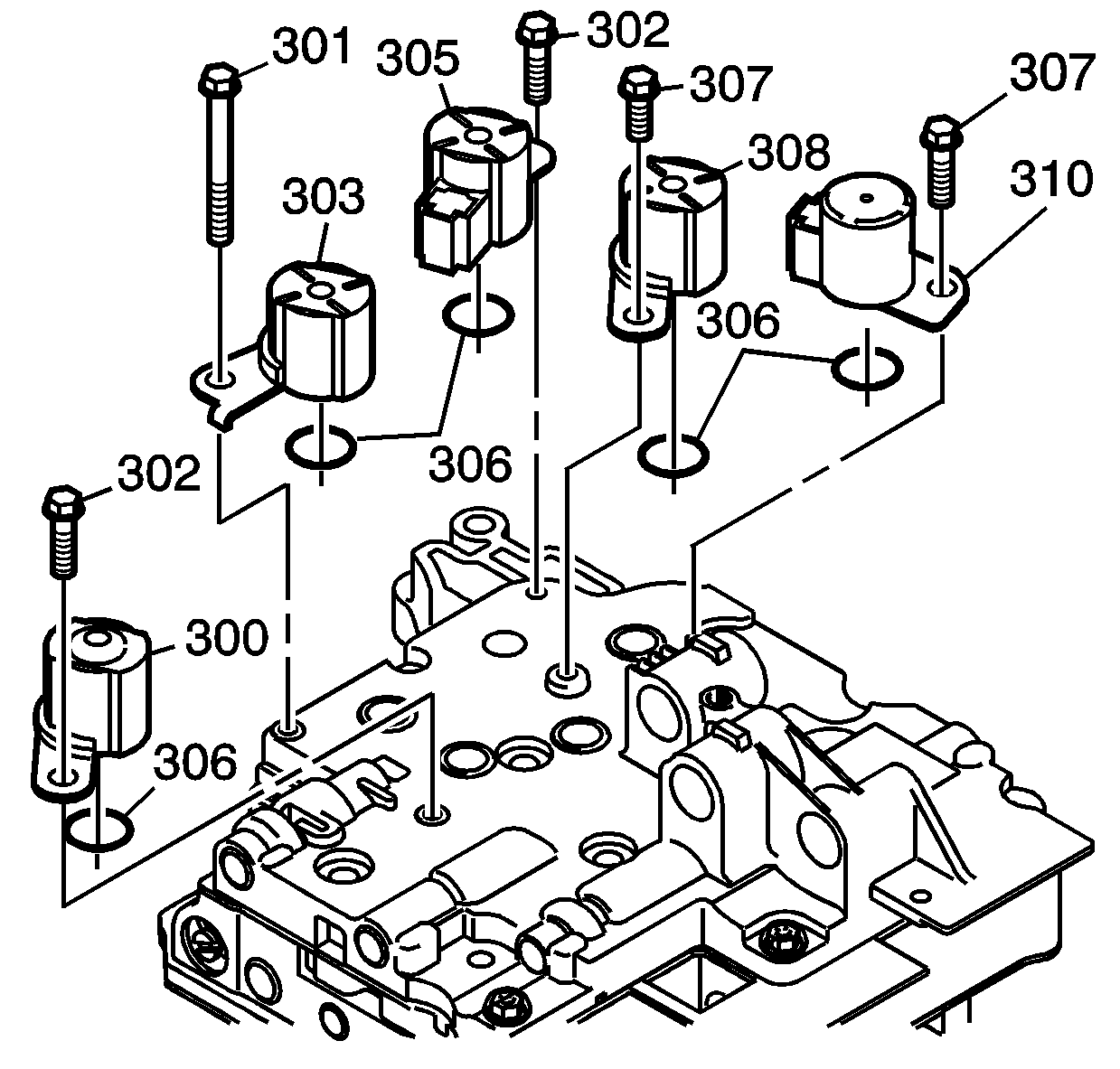
- Replace the O-ring seals (306) on each of the 5 shift solenoid valves (300, 303, 305, 308, 310).
- Install the 5 shift solenoid valves (300, 303, 305, 308, 310).
- Install the 5 shift solenoid valve retaining bolts.
- Install the 5 shift solenoid valve retaining bolts (301, 302, 307) and tighten to 7 N·m (62 lb in).
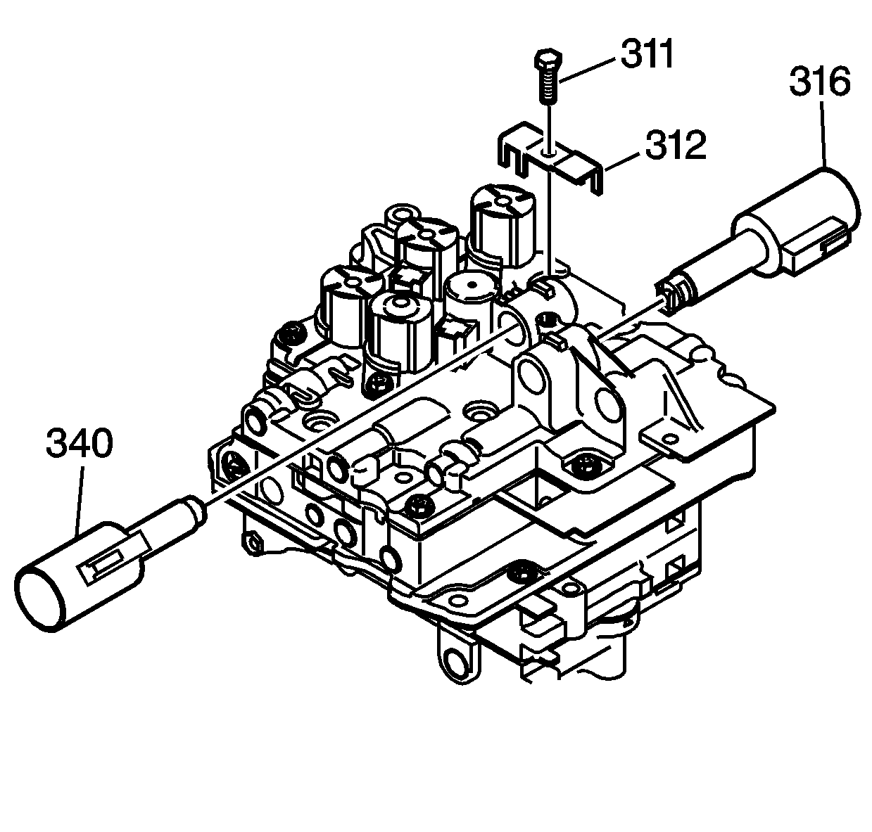
- Install the line pressure control solenoid valve assembly (316) and the shift pressure control solenoid valve assembly (340).
- Install the control valve body solenoid valve retainer (312) and 1 - M5 x 0.8 x 13 mm control valve body bolt (311) and tighten to 7 N·m (62 lb in).
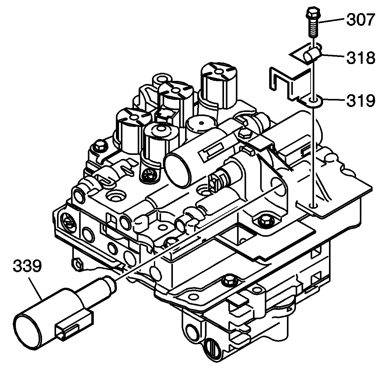
- Install the TCC lock up pressure control solenoid valve assembly (339).
- Install the TCC lock up pressure control solenoid valve retainer (319), the wiring harness clip (318), and 1 - M5 x 0.8 x 10 mm control valve body bolt/screw (307) and tighten to 7 N·m (62 lb in).
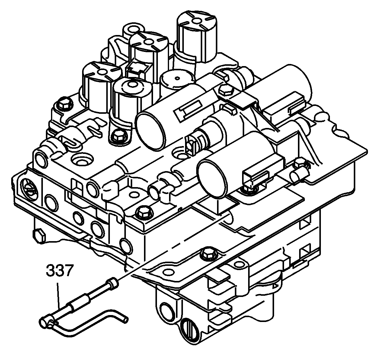
- Install the manual valve (337) into the middle control valve body assembly.
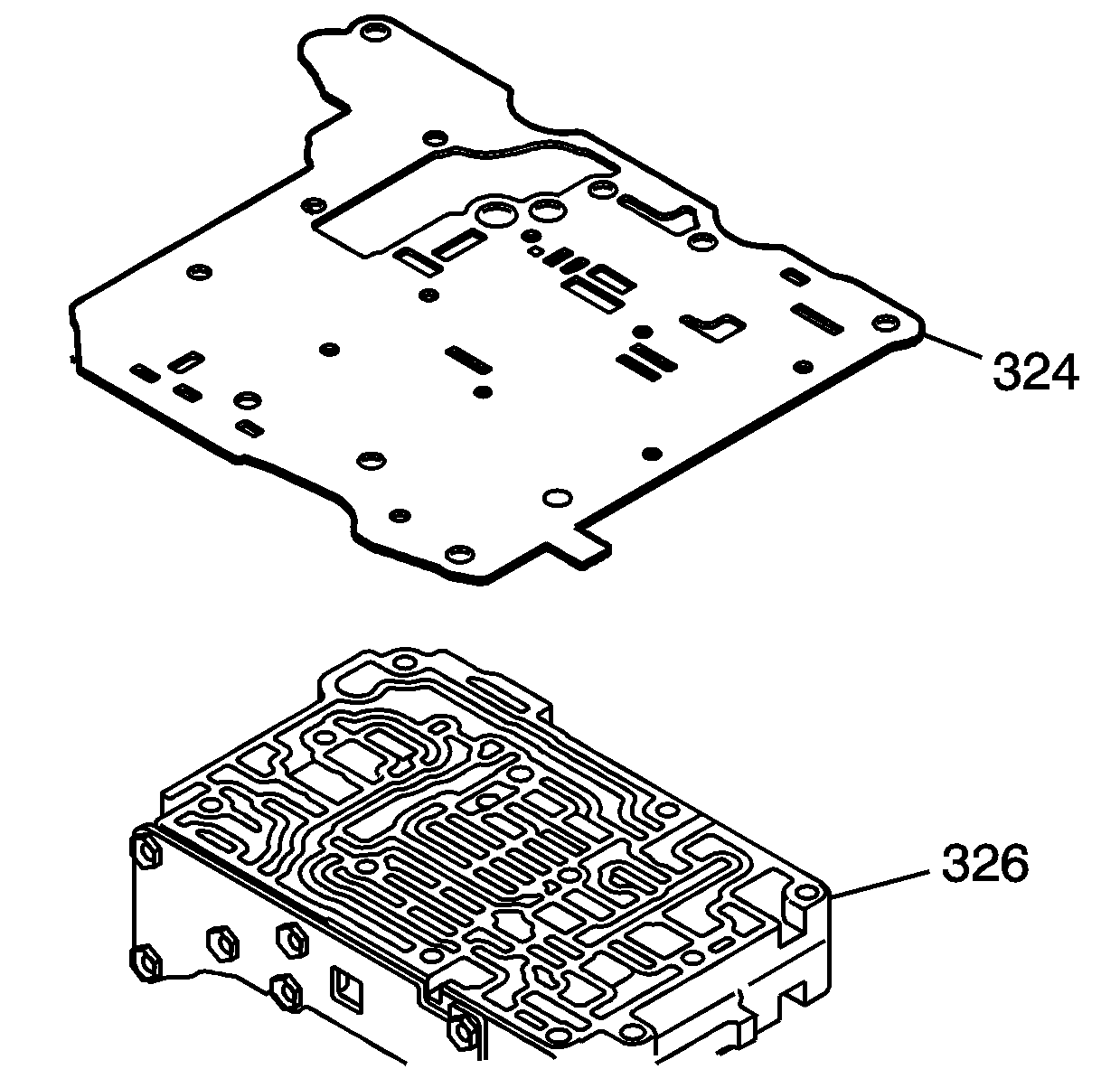
Note: Align each bolt hole in the valve body with the holes in the spacer plate and gasket assembly.
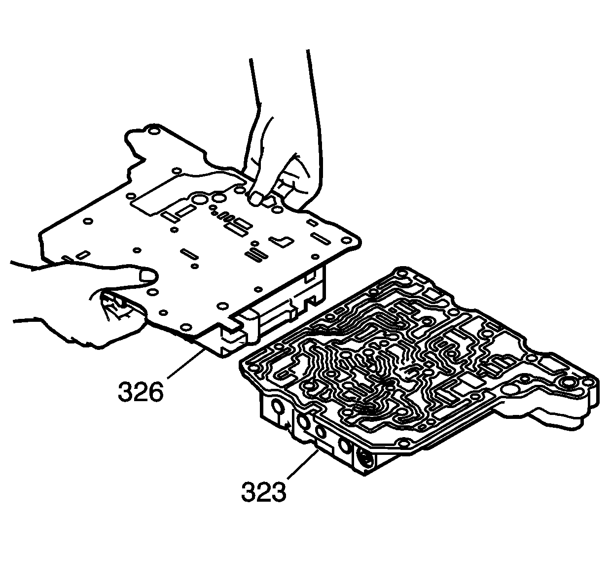
Note: Align each bolt hole in the valve body with the holes in the spacer plate and gasket assembly.
Caution: Refer to Fastener Caution in the Preface section.
Note: Align each bolt hole on the valve body with the holes in the gaskets and plates.
Note: Align each bolt hole on the valve body with the holes in the gaskets and plates.
Note: Align each bolt hole in the valve body with the holes in the gaskets and spacer plate.
Note: Align each bolt hole in the valve body with the holes in the gaskets and spacer plate.
Caution: Refer to Fastener Caution in the Preface section.
Note:
• Use NEW O-ring seals. • Do not damage the O-ring seals.
| • | 1 - (301) - M5 x 0.8 x 62 mm |
| • | 2 - (302) - M5 x 0.8 x 28 mm |
| • | 2 - (307) - M5 x 0.8 x 10 mm |
