For 1990-2009 cars only
Clutch Master Cylinder Replacement D16 and D20 Manual Transaxle
Removal Procedure
- Remove the locking clip.
- Remove the push rod fixing pin and push rod.
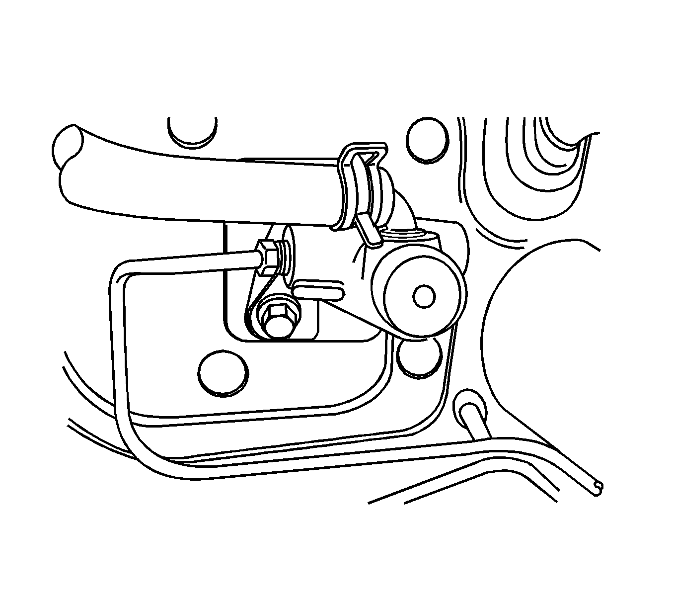
- Disconnect the hose clamp on the master cylinder.
- Disconnect the master cylinder hose.
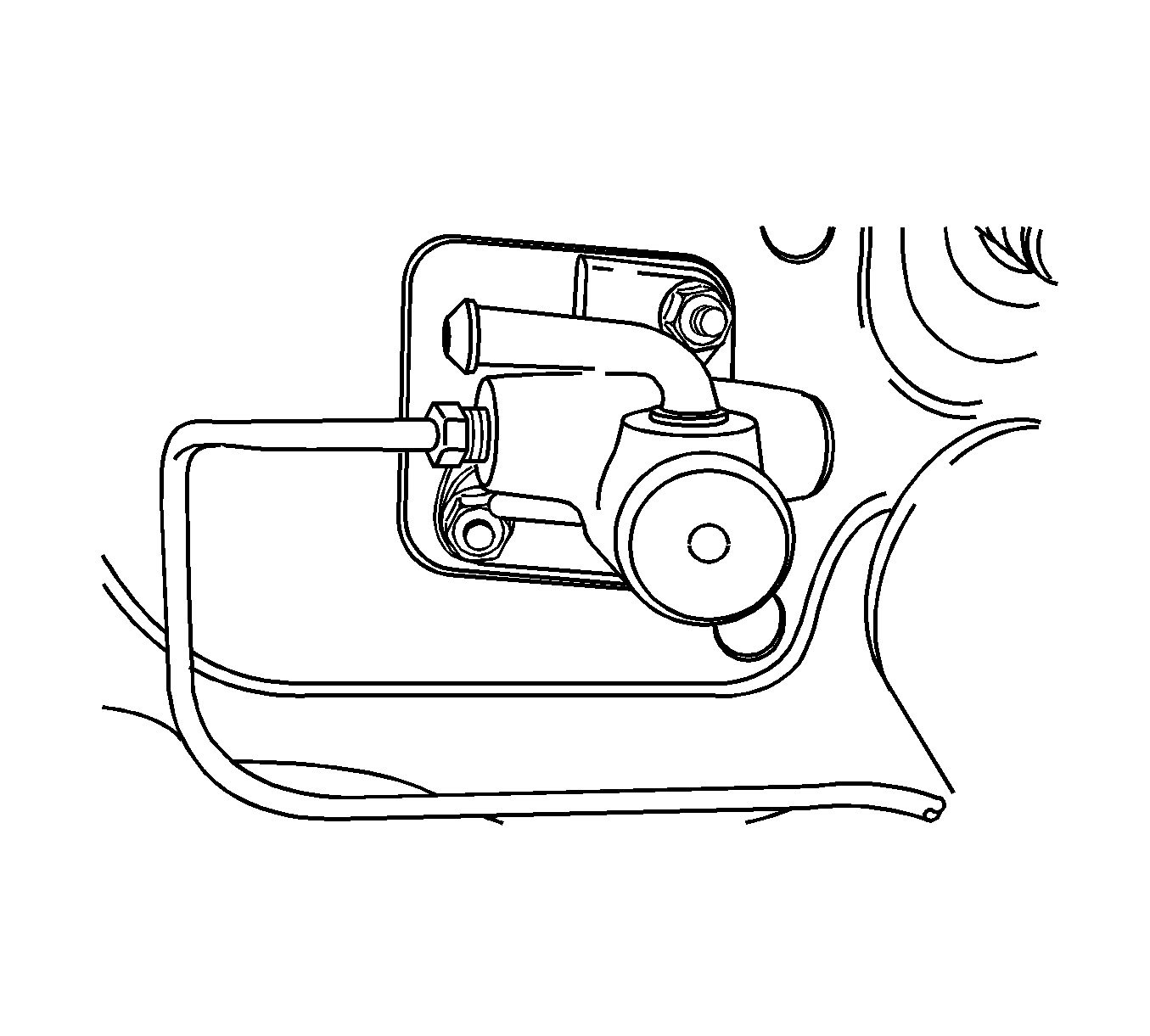
- Remove the master cylinder pipe.
- Remove the clutch master cylinder nuts.
- Remove the clutch master cylinder.
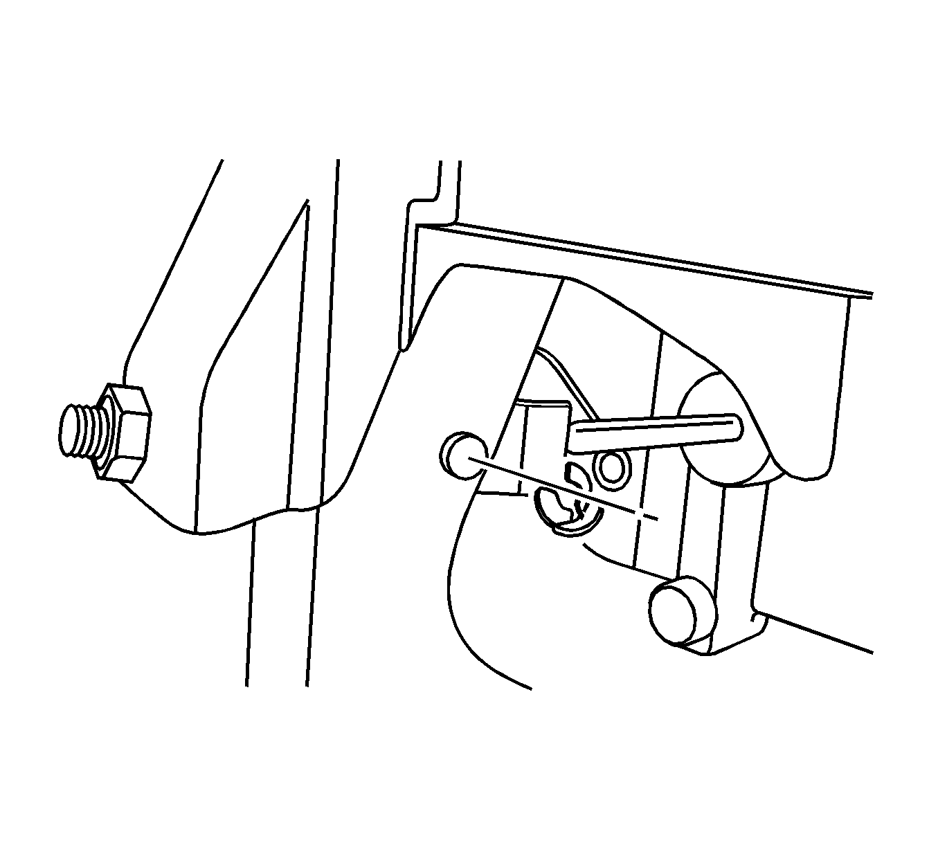
Note: Before disconnecting the reservoir tank hose, remove the clutch/brake fluid from the reservoir tank.
Installation Procedure
- Install the clutch master cylinder with clutch master cylinder nuts and tighten to 22 N·m (16 lb ft).
- Install the master cylinder pipe.
- Connect the master cylinder hose.
- Connect the hose clamp on the master cylinder.
- Install the push rod fixing pin and push rod.
- Install the locking clip.
- Bleed the air.
- Adjust the clutch pedal. Refer to Clutch Pedal Free Travel Adjustment.
- Fill the reservoir with clutch/brake fluid up to the proper level.
Caution: Refer to Fastener Caution in the Preface section.
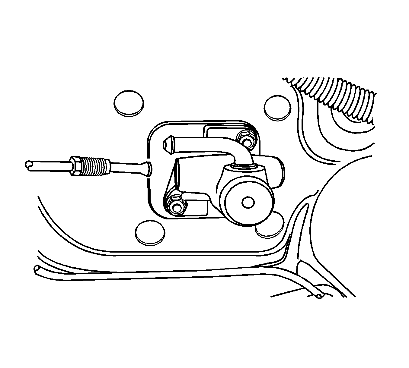


Clutch Master Cylinder Replacement D33 Manual Transaxle
Removal Procedure
- Disconnect the negative battery.
- Disconnect the spring clamp on the master cylinder.
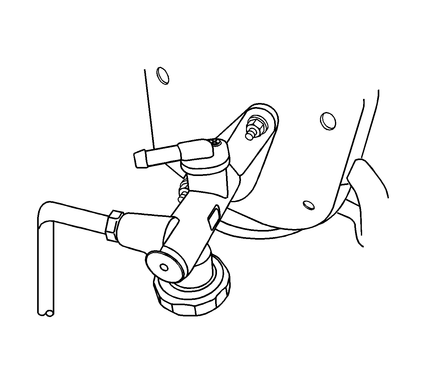
- Remove the reservoir hose.
- Disconnect the pipe connected to the master cylinder.
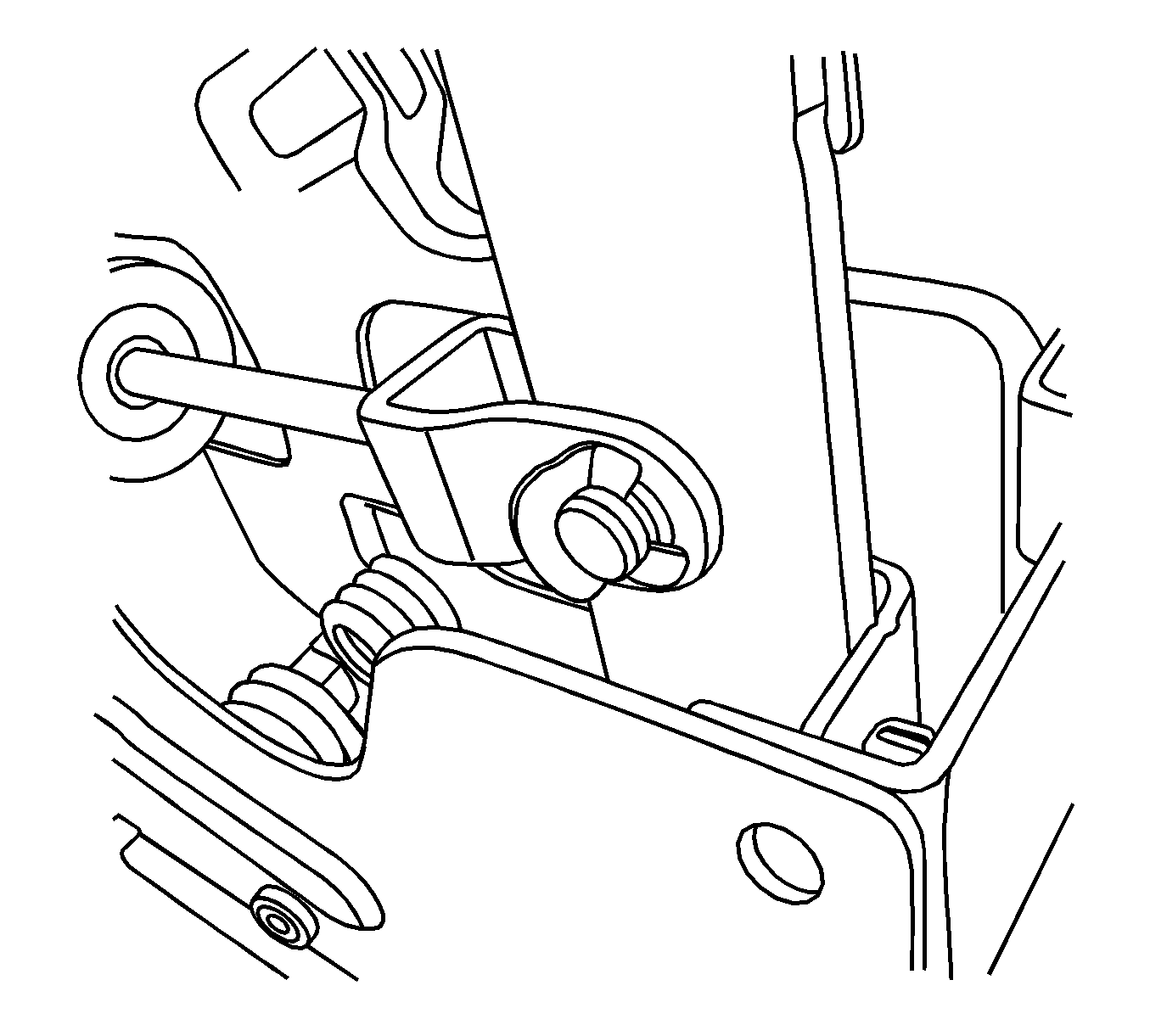
- Remove the E-ring and the push rod fixing pin from the clutch pedal and the push rod clevis.
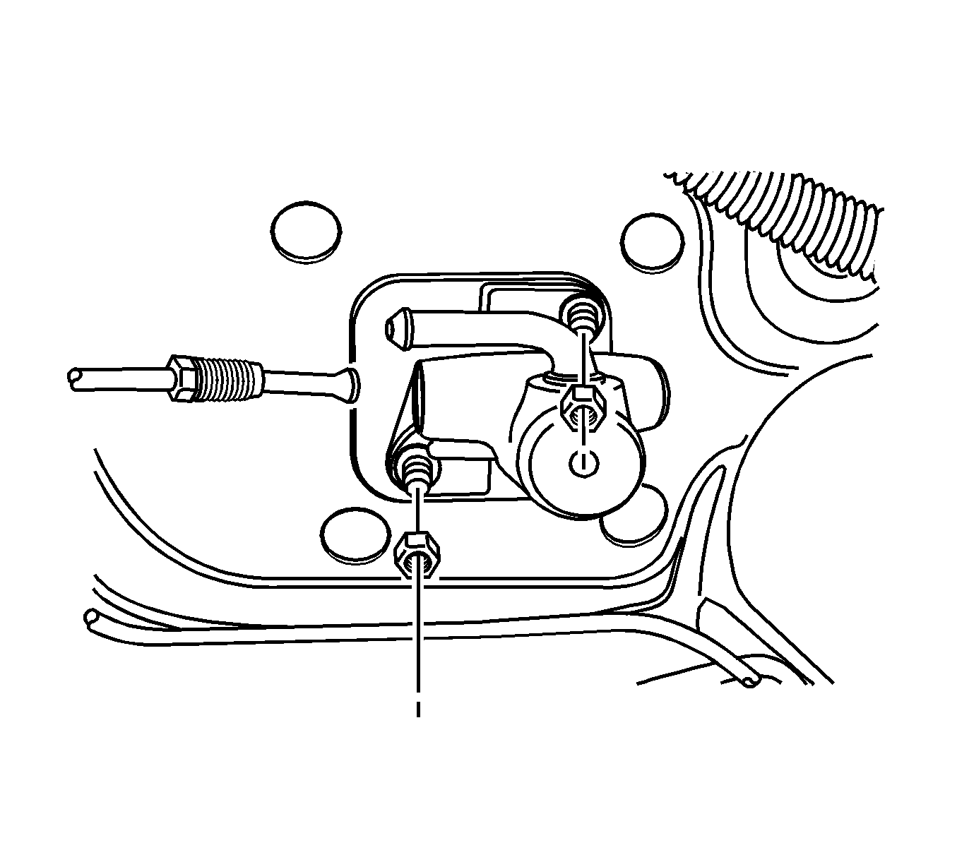
- Remove the locknuts on the master cylinder bracket. Remove the master cylinder in the direction of the engine compartment.
Warning: Refer to Battery Disconnect Warning in the Preface section.
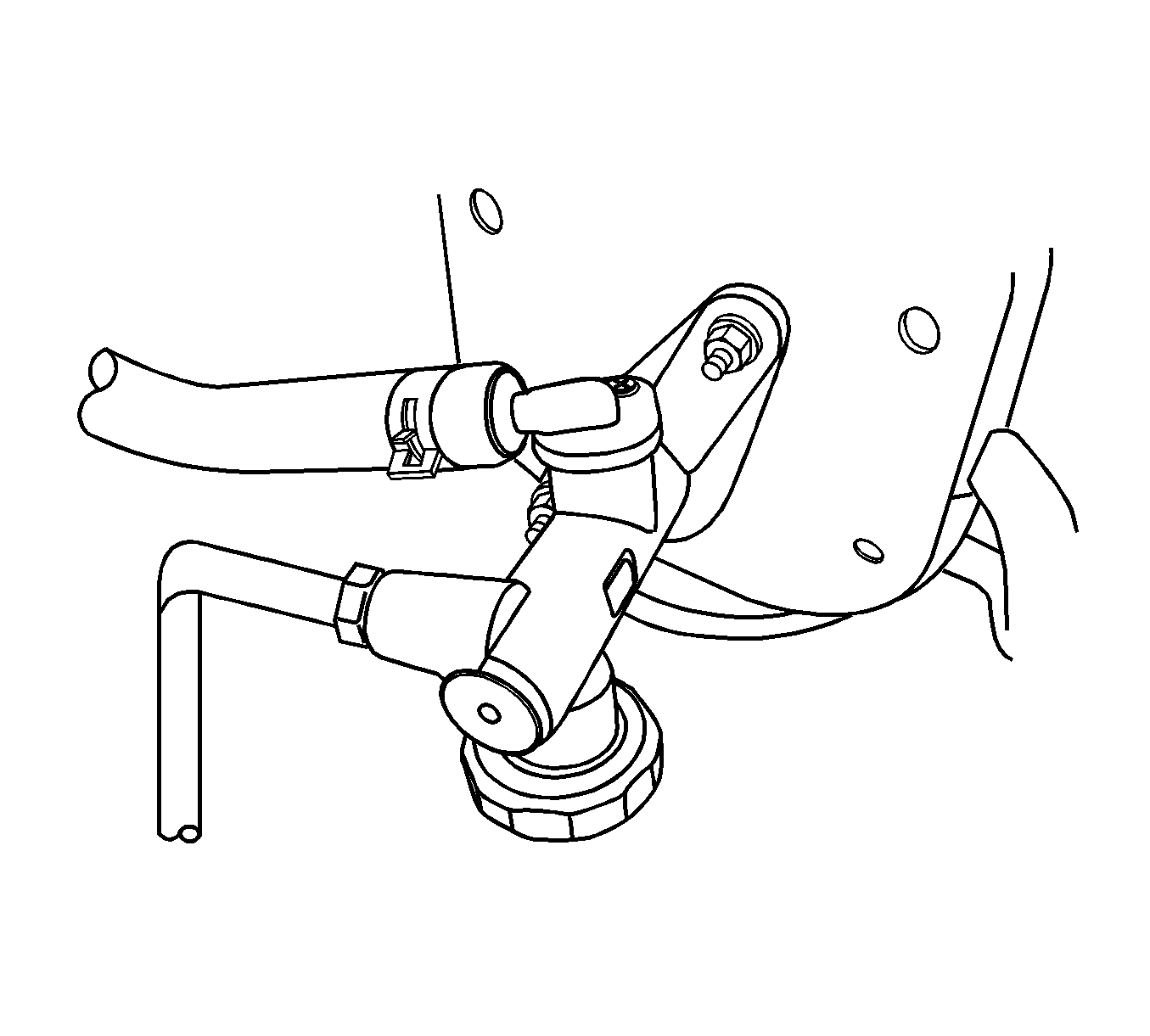
Note: Before disconnecting the reservoir tank hose, remove the clutch/brake fluid from the reservoir tank.
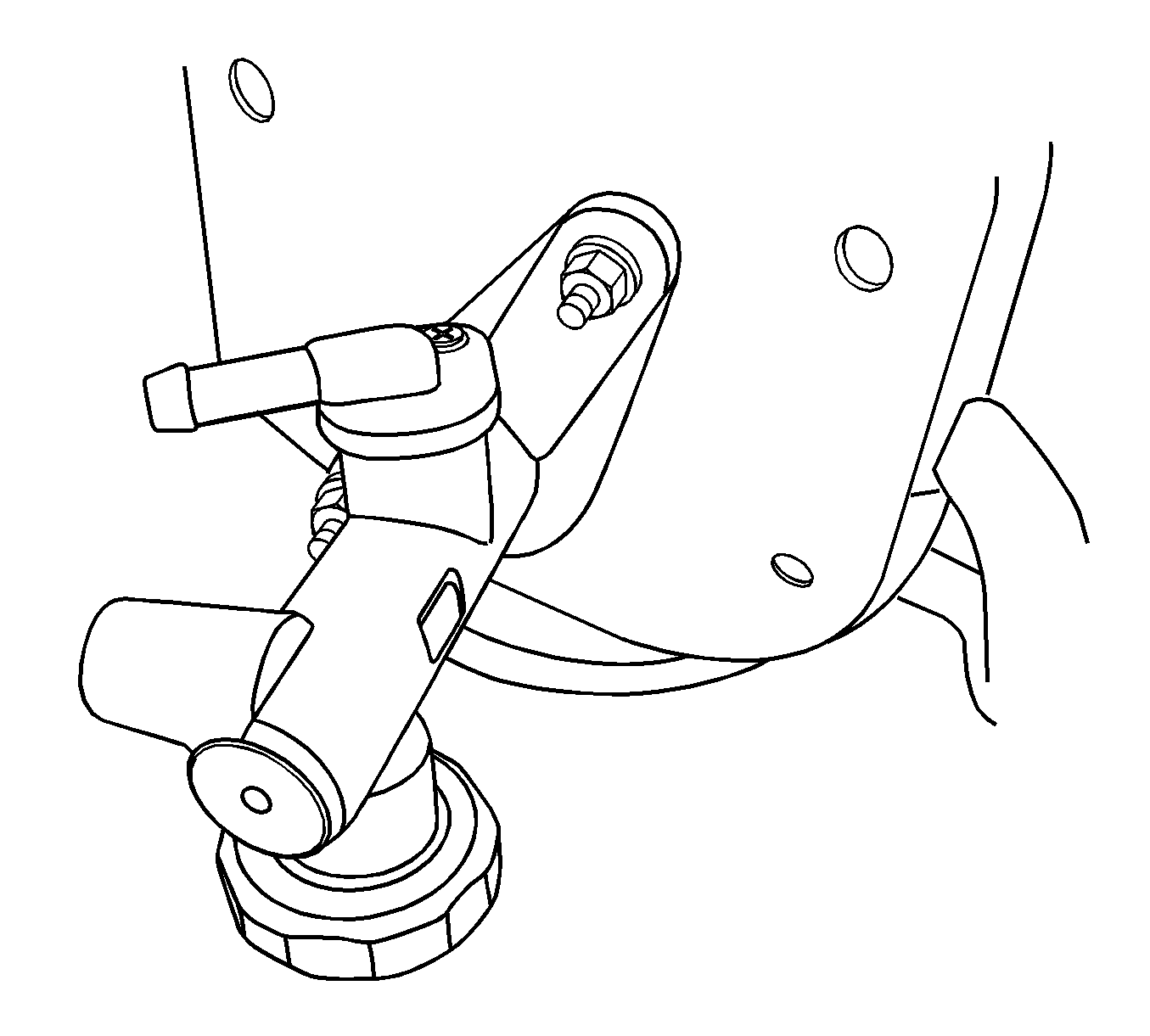
Installation Procedure
- Install the master cylinder using the mounting bolts, install the locknuts and tighten to 22 N·m (16 lb ft)..
- Connect the pipe to the master cylinder.
- Connect the reservoir hose to the master cylinder and tighten the spring clamp.
- Coat the push rod fixing pin with multi-purpose grease.
- Install the push rod clevis, the push rod fixing pin, and the E-ring onto the clutch pedal.
- Bleed the air. Refer to Hydraulic Clutch Bleeding.
- Connect the negative battery.
Caution: Refer to Fastener Caution in the Preface section.


