Tools Required
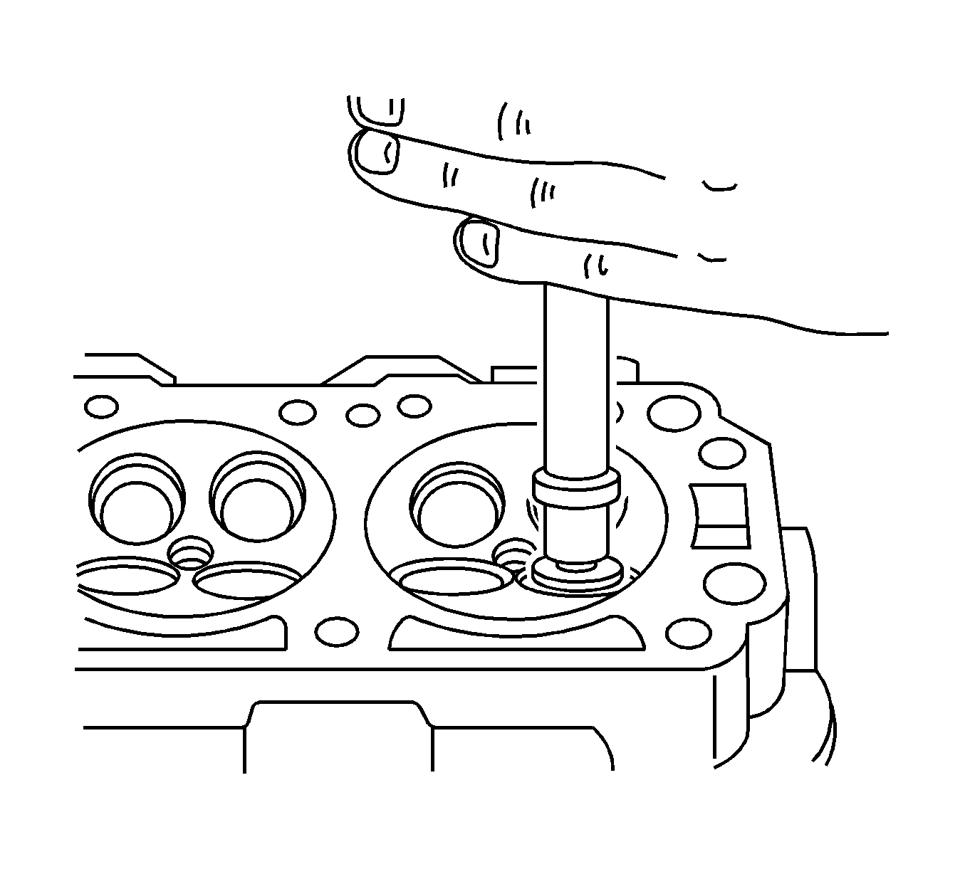
- Lubricate the valve seat using a fine-grained paste.
- Lift the valve rhythmically from the seat with a commercially available valve grinding tool in order to distribute the paste.
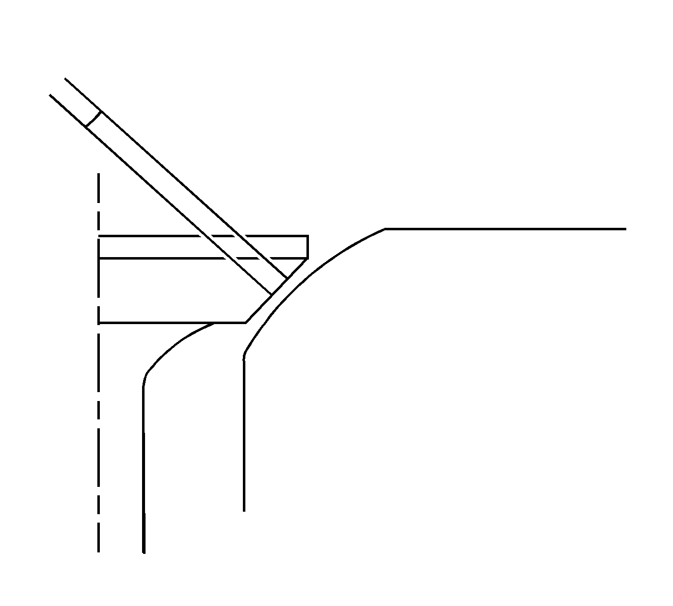
- Check the contact pattern on the valve head and in the cylinder head.
- Clean the valves the valve guides and the cylinder head.
Valve Grind
Caution: Refer to Safety Glasses Caution in the Preface section.
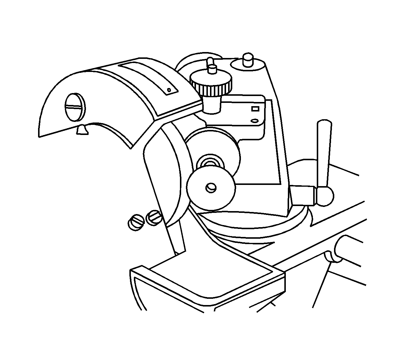
- Ensure that there are no crater line burns on the valve cone.
- The valve may be reground only two times. Do not grind the valve stem end.
- Ensure that the angle at the valve face is 45 degrees.
- Inspect the assembly height of the intake valves and the exhaust valves.
Valve Guide - Ream
Caution: Refer to Safety Glasses Caution in the Preface section.
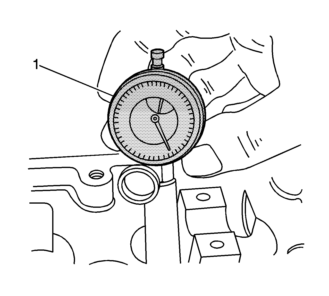
- Measure the diameter of the valve guide using
KM-571-B
(1) and a commercially available inside micrometer.
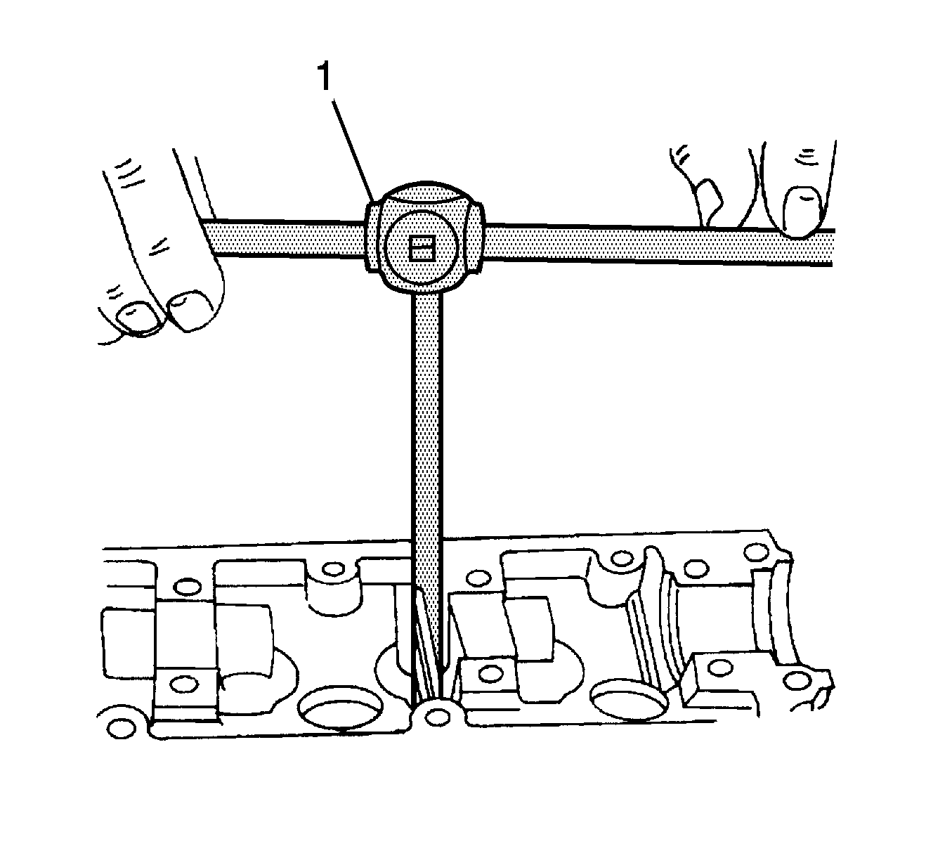
Important: Oversized valves may already have been fitted in production.
- An oversize service code is on the valve guide and the valve stem end. The Valve Guide Reaming table gives the correct size, reamer, and production code for each service code. Refer to the Valve Guide Reaming table in
Engine Mechanical Specifications
.
- Using
KM-805
, ream the valve guide from the upper side of the cylinder head to the next oversize.
- After reaming, cross out the code and emboss the valve guide with the new code.
Valve Seat - Cut
Caution: Refer to Safety Glasses Caution in the Preface section.
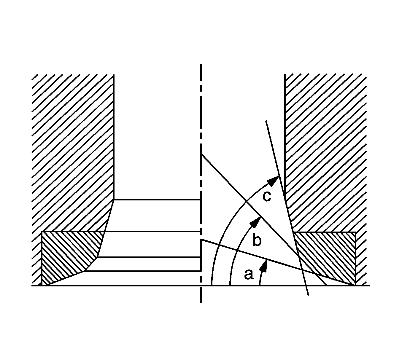
- Place the cylinder head on wooden blocks.
- Cut the intake and the exhaust valve seats using KM-340-7 Guide Drift as follows:
| • | Valve seat - A 45-degree (b) surface using the cutter KM-340-13. |
| • | Upper correction angle - A 30-degree (a) surface using the cutter KM-340-13. |
| • | Lower correction angle - A 60-degree (c) surface using the cutter KM-340-26. |
- Clean the chippings from the cylinder head.
- Inspect the dimension for the valve seat width.
Specifications
| • | Intake: 1.2-1.4 mm (0.047-0.055 in) |
| • | Exhaust: 1.4-1.8 mm (0.055-0.070 in) |
- Inspect the assembly height of the intake valves and the exhaust valves. If the dimension is exceeded. Install new valves. Inspect the assembly height of the intake valves and the exhaust valves again. If the valve assembly height is still too large
despite replacing the valves, replace the cylinder head.


