For 1990-2009 cars only
Removal Procedure
- Raise and suitably support the vehicle. Refer to Lifting and Jacking the Vehicle .
- Mark the position of the wheels relative to the wheel hubs and remove the rear wheels. Refer to Tire and Wheel Removal and Installation .
- Loosen the parking brake cable. Refer to Park Brake Adjustment .
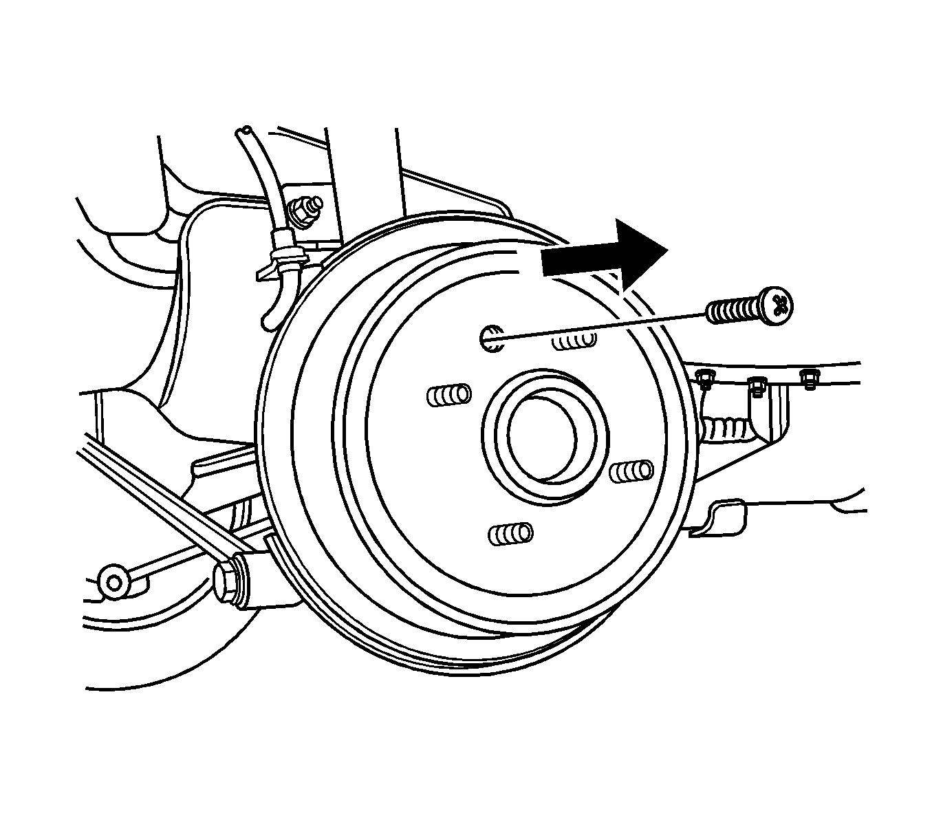
- Remove the drum detent screw and the brake drum.
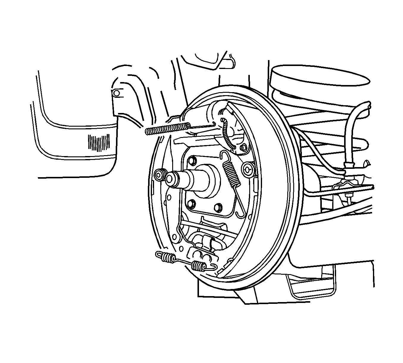
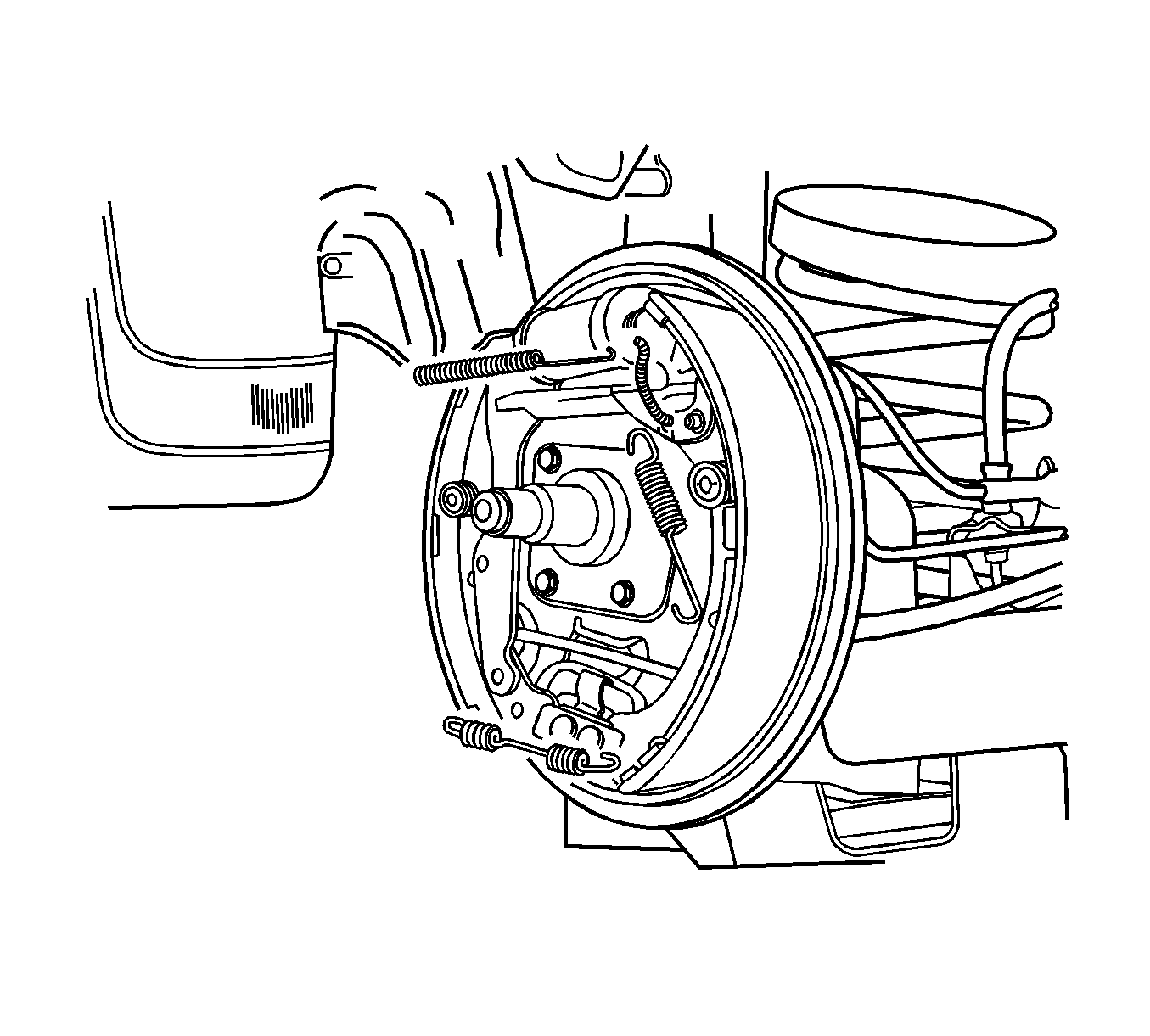
- Loosen the leading shoe hold-down return spring. The ABS braking system configuration is illustrated.
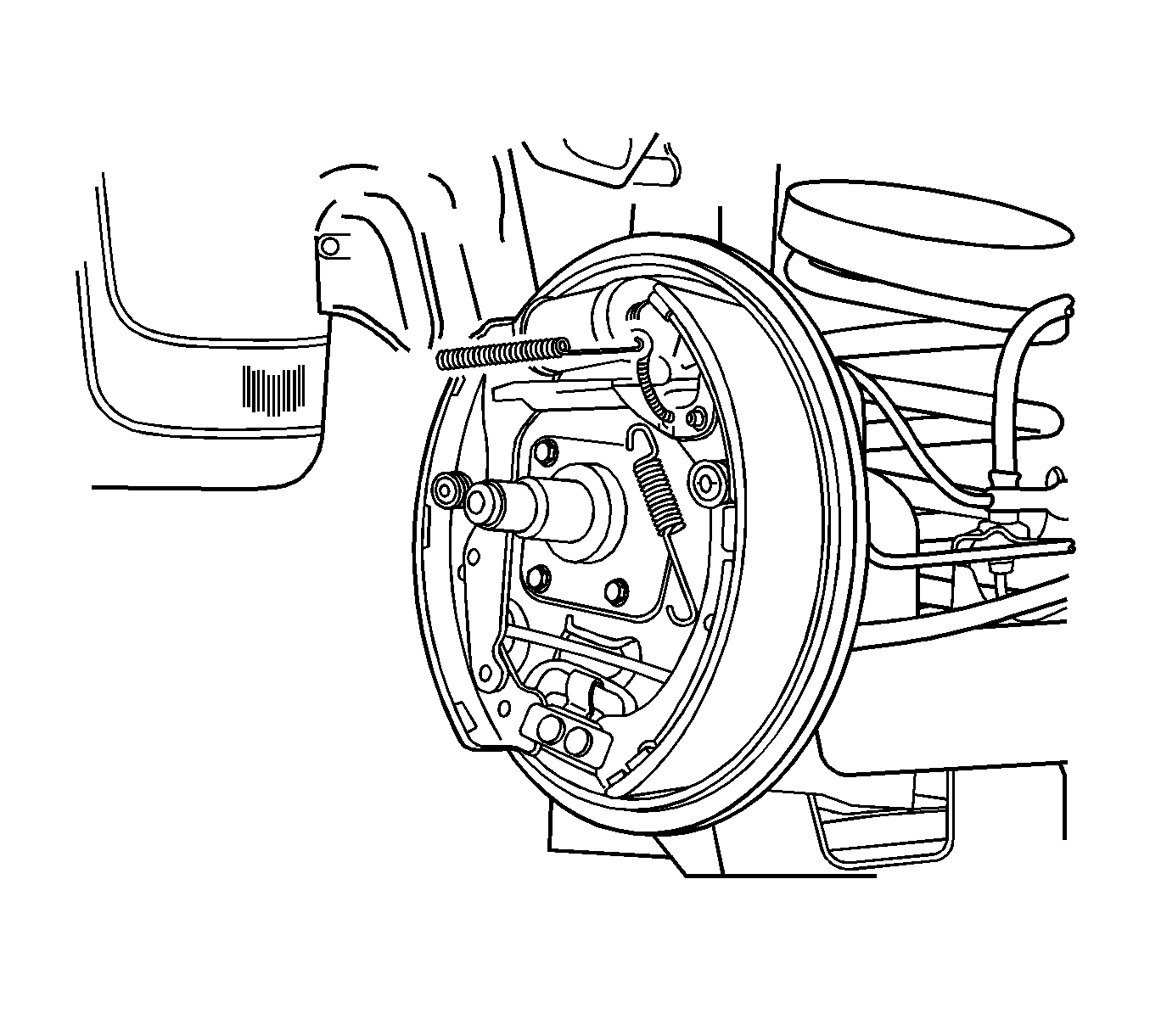
- Disconnect the upper link of the connecting link spring of the leading shoe to relieve tension on the upper return spring.
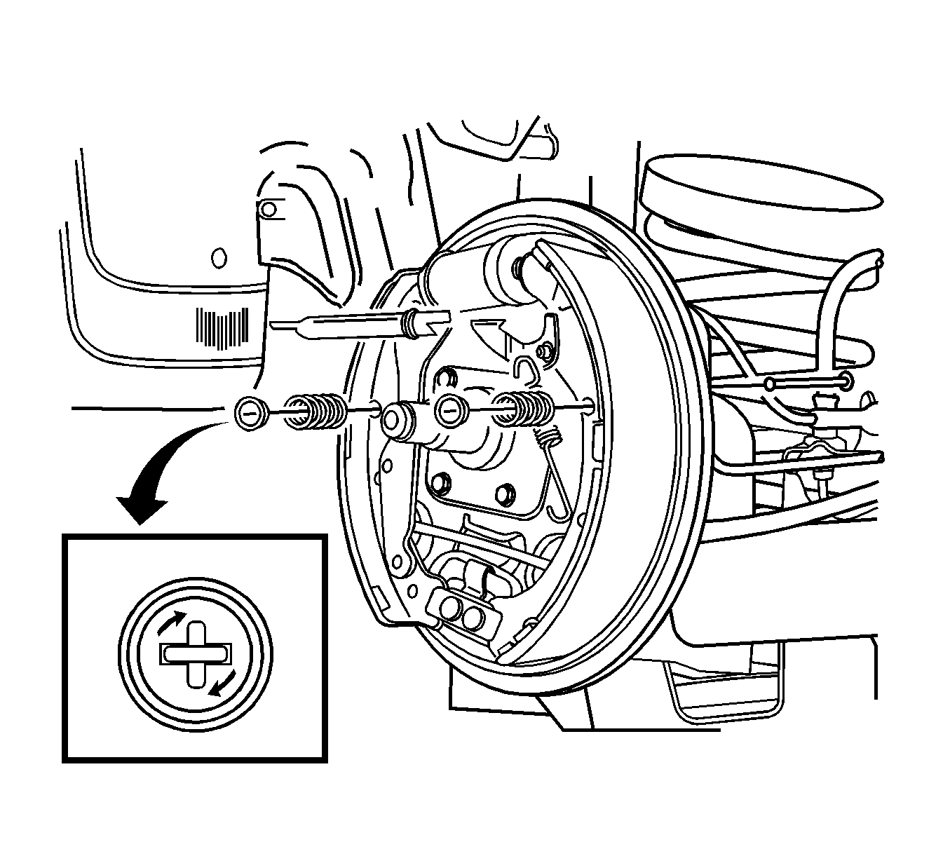
- Remove the upper return spring and the adjuster.
- Unfasten the trailing shoe and lining assembly hold-down return spring.
- Disconnect the trailing shoe and lining assembly on the right side.
- Detach the lower return spring.
Installation Procedure
- Measure the minimum brake lining thickness. Refer to Brake Shoe Inspection .
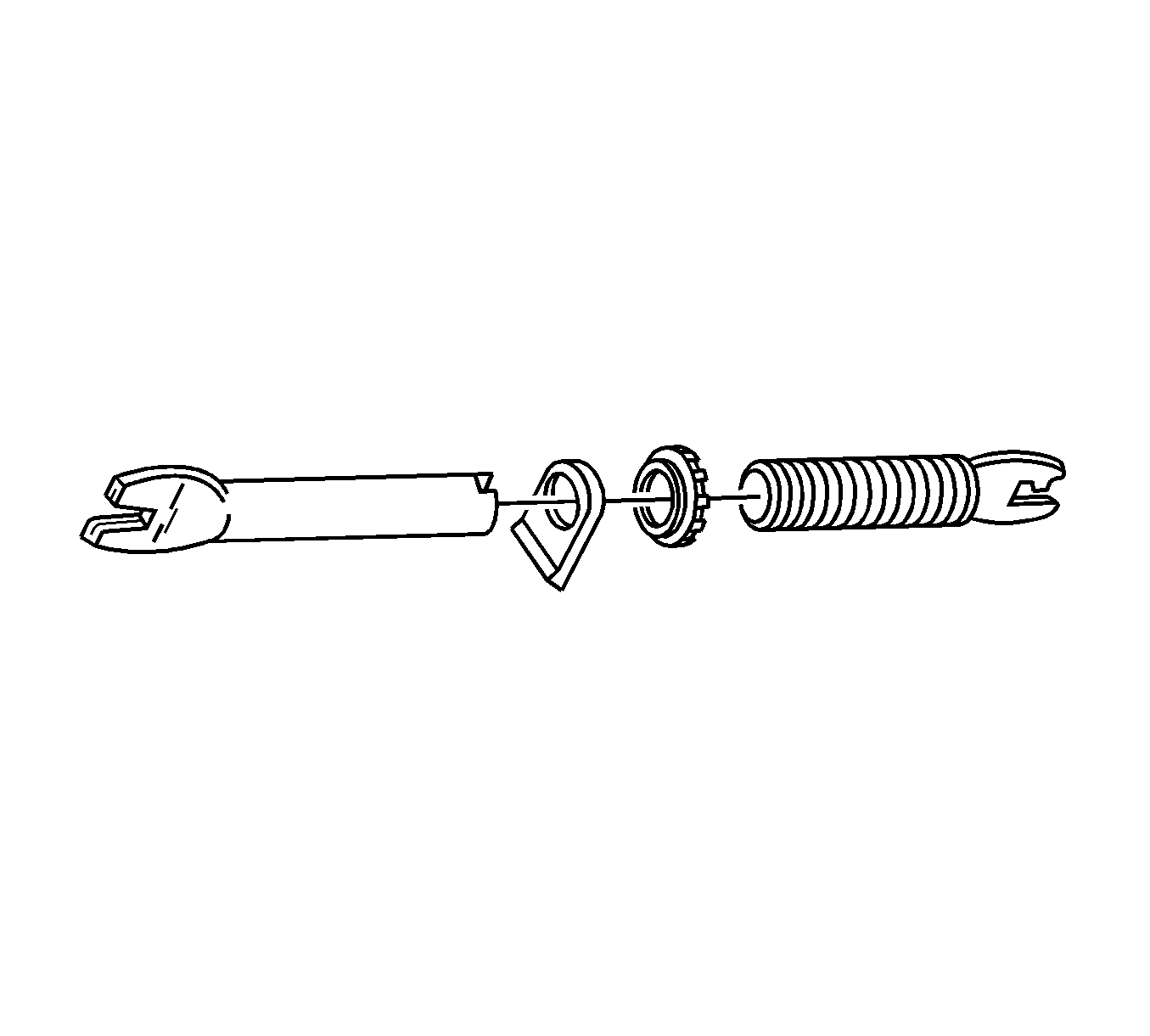
- Clean the adjuster assembly and apply grease.
- Inspect the threads of the adjuster assembly for smooth rotation.
- Install the trailing shoe and lining assembly with the hold-down spring, the washer, and the pin.
- Ensure the parking brake cable is properly routed and attached to the shoe lever.
- Fasten the lower return spring on the shoe.
- Position the leading shoe and the adjuster assembly against the backing plate.
- Fasten the lower return spring to the leading shoe.
- Install the adjuster assembly.
- Turn the adjuster in as far as possible.
- Position the spring clip toward the backing plate.
- Install the leading shoe with the hold-down spring.
- Attach the leading shoe upper link-spring connection, which applies tension to the upper return spring.
- Install the upper return spring from the spring connecting link to the brake shoe.
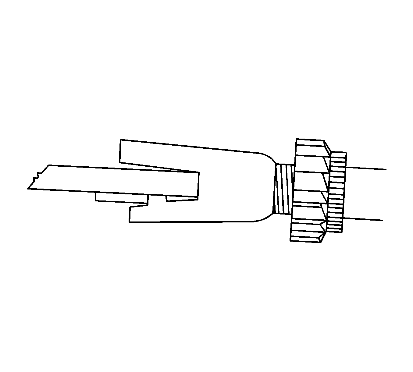
- Before installing the brake drum, make sure the adjuster assembly nut is drawn all the way to the stop.
- Install the brake drum.
- Install the detent screw.
- Test the amount of drag on the drum brake. If the amount of drag is not sufficient, adjust the drum brake. Refer to Drum Brake Adjustment .
- Install the rear wheels. Refer to Tire and Wheel Removal and Installation .
- Lower the vehicle.
- Apply the brake more than 10 times until the clicking of the adjustment actuator can no longer be heard.
- Adjust the park brake. Refer to Park Brake Adjustment .
Important: If any parts are of questionable strength or quality because of heat discoloration, excessive stress, or wear, the shoes, the springs, or the adjuster assembly should be replaced.

Important: Do not overstretch the lower return spring.


Important: Do not overstretch the upper return spring.
Important: The nut must not lock firmly at the end of the adjustment assembly.

Notice: Refer to Fastener Notice in the Preface section.
Tighten
Tighten the drum detent screw to 4 N·m (35 lb in).
Important: The brake pedal must be operated more than 10 times. When the clicking noise can no longer be heard, the clearance between the brake shoe and the drum is adjusted.
