Engine Controls Connector End Views w/o Throttle Actuator Control
| Table 1: | Camshaft Position (CMP) Sensor |
| Table 2: | Crankshaft Position (CKP) Sensor |
| Table 3: | Engine Coolant Temperature (ECT) Sensor |
| Table 4: | Evaporative Emission (EVAP) Canister Purge Solenoid Valve |
| Table 5: | Evaporative Emission (EVAP) Canister Vent Solenoid Valve |
| Table 6: | Exhaust Gas Recirculation (EGR) Valve |
| Table 7: | Fuel Injector 1 |
| Table 8: | Fuel Injector 2 |
| Table 9: | Fuel Injector 3 |
| Table 10: | Fuel Injector 4 |
| Table 11: | Fuel Pump |
| Table 12: | Heated Oxygen Sensor 1 (HO2S1) |
| Table 13: | Heated Oxygen Sensor 2 (HO2S2) |
| Table 14: | Heated Oxygen Sensor 2 (HO2S2) (Mexico,Japan) |
| Table 15: | Idle Air Control (IAC) Valve |
| Table 16: | Ignition Coil (IC) Module |
| Table 17: | Intake Air Temperature (IAT) Sensor |
| Table 18: | Intake Manifold Tuning Valve Solenoid |
| Table 19: | Knock Sensor (KS) |
| Table 20: | Manifold Absolute Pressure (MAP) Sensor |
| Table 21: | Rough Road Sensor |
| Table 22: | Throttle Position (TP) Sensor |
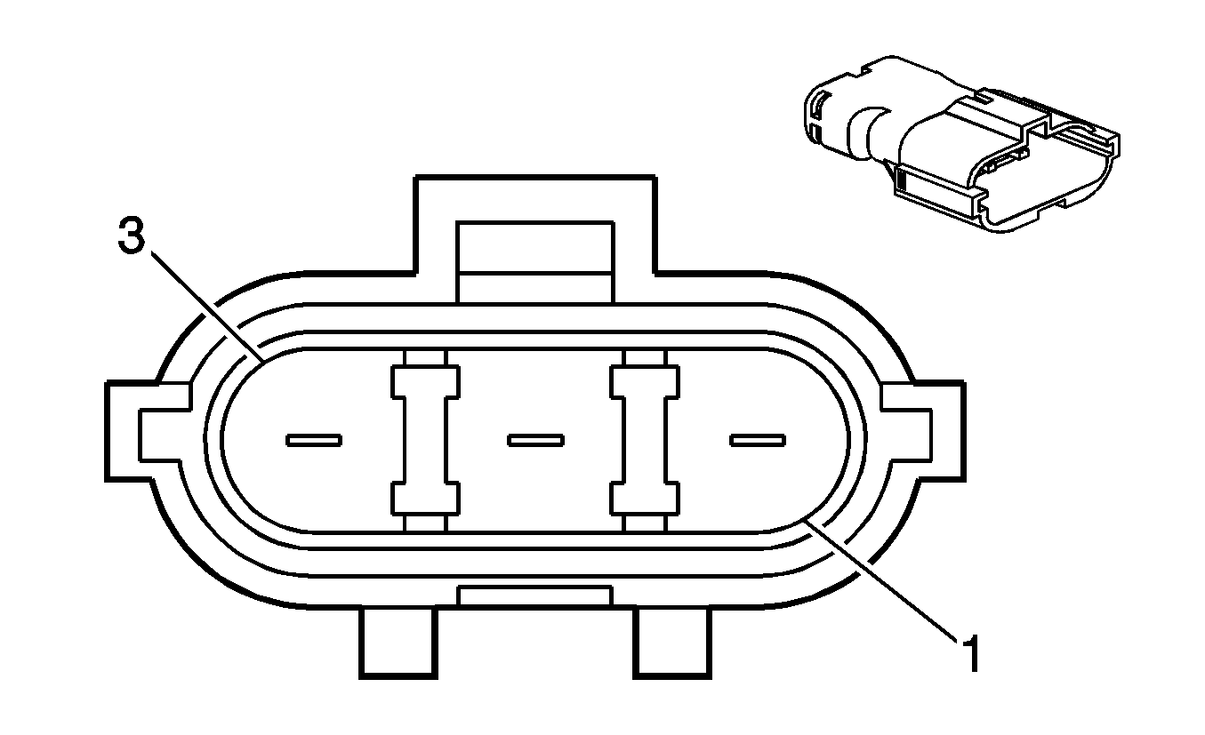
| |||||||
|---|---|---|---|---|---|---|---|
Connector Part Information |
| ||||||
Pin | Wire Color | Circuit No. | Function | ||||
1 | PK/BK | 1846 | Ignition 1 Voltage | ||||
2 | BK/WH | 251 | Ground | ||||
3 | PU (BN/WH) | 633 | Camshaft Position (CMP) Sensor Signal | ||||
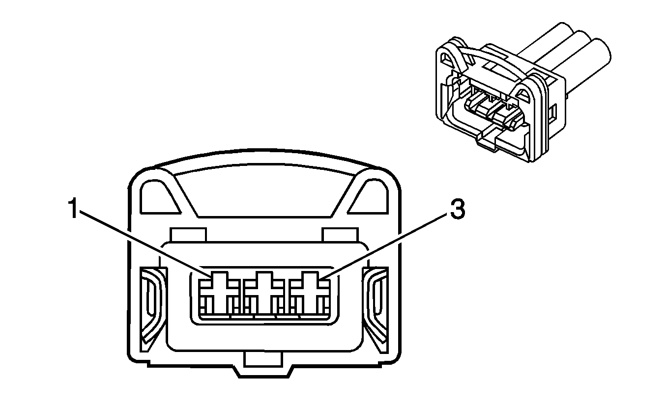
| |||||||
|---|---|---|---|---|---|---|---|
Connector Part Information |
| ||||||
Pin | Wire Color | Circuit No. | Function | ||||
1 | D-BU/WH | 1869 | Crankshaft Position (CKP) Sensor Signal | ||||
2 | YE/BK | 1868 | Low Reference | ||||
3 | BK/WH | 51 | Ground | ||||
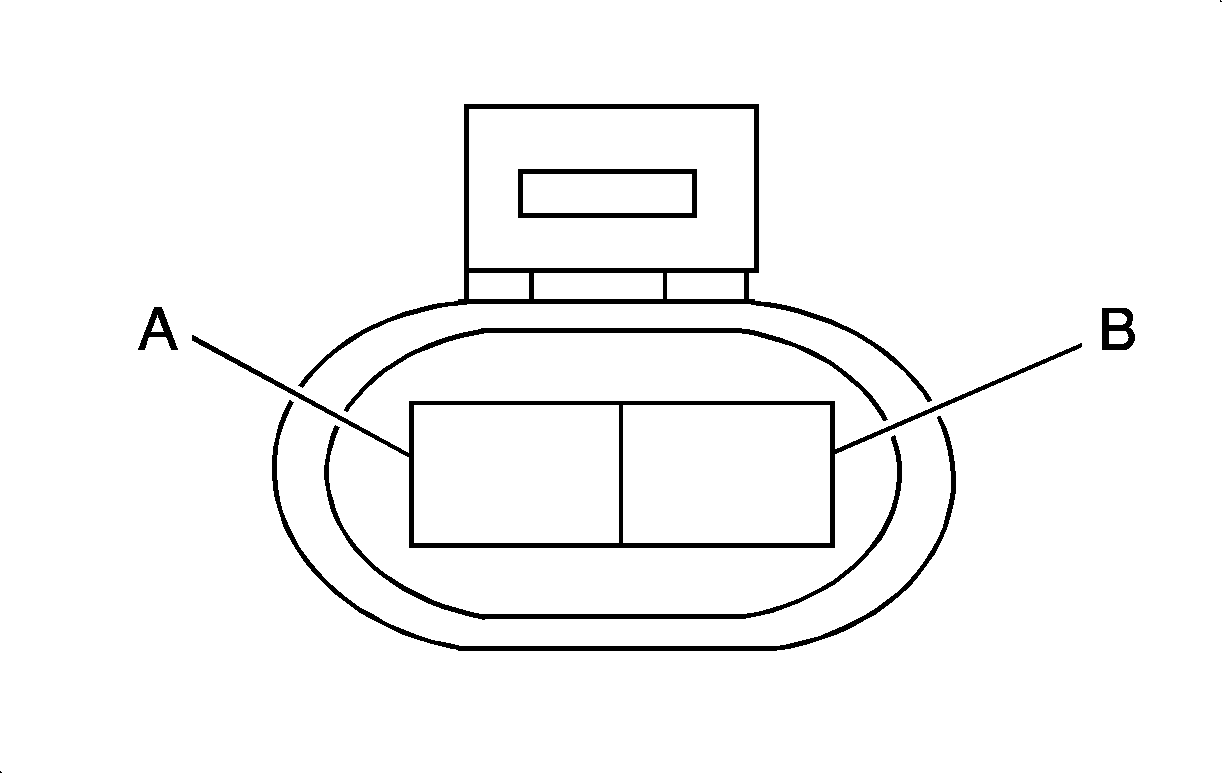
| |||||||
|---|---|---|---|---|---|---|---|
Connector Part Information |
| ||||||
Pin | Wire Color | Circuit No. | Function | ||||
A | BK (BK/YE) | 808 | Low Reference | ||||
B | L-GN (YE) | 410 | Engine Coolant Temperature (ECT) Sensor Signal | ||||
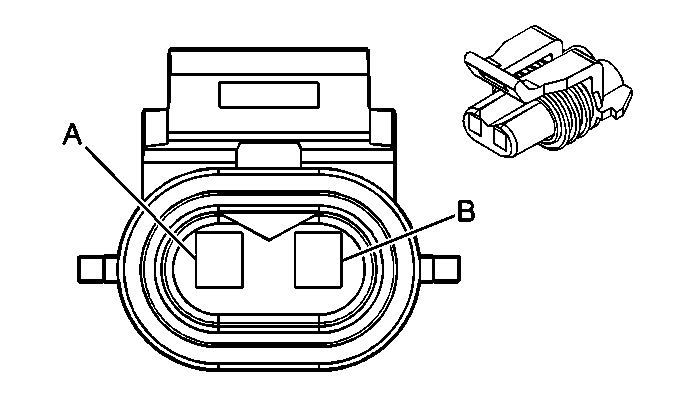
| |||||||
|---|---|---|---|---|---|---|---|
Connector Part Information |
| ||||||
Pin | Wire Color | Circuit No. | Function | ||||
1 | PK/BK | 1846 | Ignition 1 Voltage | ||||
2 | WH | 428 | Evaporative Emission (EVAP) Canister Purge Solenoid Control | ||||

| |||||||
|---|---|---|---|---|---|---|---|
Connector Part Information |
| ||||||
Pin | Wire Color | Circuit No. | Function | ||||
1 | PK/BK | 1846 | Ignition 1 Voltage | ||||
2 | L-BU/PU | 428 | Evaporative Emission (EVAP) Canister Vent Solenoid Control | ||||
| |||||||
|---|---|---|---|---|---|---|---|
Connector Part Information |
| ||||||
Pin | Wire Color | Circuit No. | Function | ||||
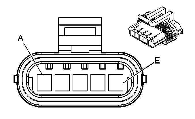
1 | D-GN | 435 | Exhaust Gas Recirulation (EGR) Solenoid Low Control | ||||
2 | OG/BK | 469 | Low Reference | ||||
3 | WH/BK | 1456 | Exhaust Gas Recirulation (EGR) Valve Position Signal | ||||
4 | L-BU/BK | 1688 | 5-Volt Reference | ||||
5 | GY | 120 | Fuel Pump Supply Voltage | ||||
| |||||||
|---|---|---|---|---|---|---|---|
Connector Part Information |
| ||||||
Pin | Wire Color | Circuit No. | Function | ||||
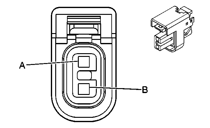
A | YE/BU (BK) | 1744 | Fuel Injector 1 Control | ||||
B | PK | 139 | Ignition 1 Voltage | ||||

| |||||||
|---|---|---|---|---|---|---|---|
Connector Part Information |
| ||||||
Pin | Wire Color | Circuit No. | Function | ||||
A | BN/WH (L-GN/BK) | 1745 | Fuel Injector 2 Control | ||||
B | PK | 139 | Ignition 1 Voltage | ||||

| |||||||
|---|---|---|---|---|---|---|---|
Connector Part Information |
| ||||||
Pin | Wire Color | Circuit No. | Function | ||||
A | D-GN/BK (PK/BK) | 1746 | Fuel Injector 3 Control | ||||
B | PK | 139 | Ignition 1 Voltage | ||||

| |||||||
|---|---|---|---|---|---|---|---|
Connector Part Information |
| ||||||
Pin | Wire Color | Circuit No. | Function | ||||
A | D-GN/WH (L-BU/BK) | 844 | Fuel Injector 4 Control | ||||
B | PK | 139 | Ignition 1 Voltage | ||||
| |||||||
|---|---|---|---|---|---|---|---|
Connector Part Information |
| ||||||
Pin | Wire Color | Circuit No. | Function | ||||
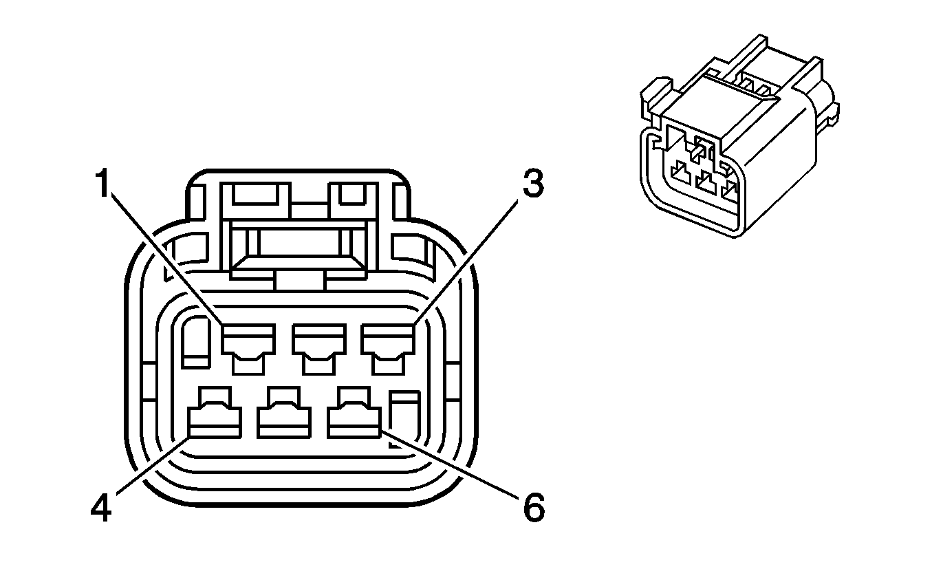
1 | D-BU | 1936 | Fuel Level Sensor Signal | ||||
2 | BK | 1250 | Ground | ||||
3 | GY | 120 | Fuel Pump Supply Voltage | ||||
4 | BK | 1250 | Ground | ||||
5 | PU | 172 | Low Fuel Indicator Control | ||||
6 | PU/BK | 632 | Low Reference | ||||
| |||||||
|---|---|---|---|---|---|---|---|
Connector Part Information |
| ||||||
Pin | Wire Color | Circuit No. | Function | ||||
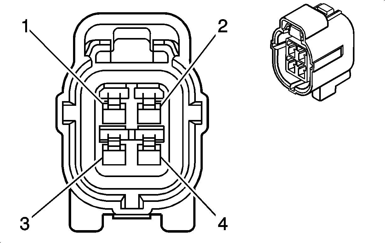
1 | D-GN/RD | 1665 | Heated Oxygen Sensor (HO2S) 1 Low Reference | ||||
2 | PK/BK | 1846 | Ignition 1 Voltage | ||||
3 | GY | 1653 | Heated Oxygen Sensor (HO2S) 1 Signal | ||||
4 | BN/WH | 1669 | Heated Oxygen Sensor (HO2S) 1 Heater Control | ||||

| |||||||
|---|---|---|---|---|---|---|---|
Connector Part Information |
| ||||||
Pin | Wire Color | Circuit No. | Function | ||||
1 | PU | 1670 | Heated Oxygen Sensor (HO2S) 2 Signal | ||||
2 | PK/BK | 1846 | Ignition 1 Voltage | ||||
3 | L-GN | 413 | Heated Oxygen Sensor (HO2S) 2 Low Reference | ||||
4 | BN/BK | 1671 | Heated Oxygen Sensor (HO2S) 2 Heater Control | ||||

| |||||||
|---|---|---|---|---|---|---|---|
Connector Part Information |
| ||||||
Pin | Wire Color | Circuit No. | Function | ||||
1 | PK/BK | 1846 | Ignition 1 Voltage | ||||
2 | PU | 1670 | Heated Oxygen Sensor (HO2S) 2 Signal | ||||
3 | BN/BK | 1671 | Heated Oxygen Sensor (HO2S) 2 Heater Control | ||||
4 | L-GN | 413 | Heated Oxygen Sensor (HO2S) 2 Low Reference | ||||
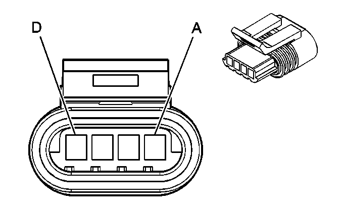
| |||||||
|---|---|---|---|---|---|---|---|
Connector Part Information |
| ||||||
Pin | Wire Color | Circuit No. | Function | ||||
A | WH | 444 | Idle Air Control (IAC) Coil B Low Control | ||||
B | PU/WH | 1749 | Idle Air Control (IAC) Coil B High Control | ||||
C | YE/WH | 1748 | Idle Air Control (IAC) Coil A Low Control | ||||
D | BN | 1747 | Idle Air Control (IAC) Coil A High Control | ||||
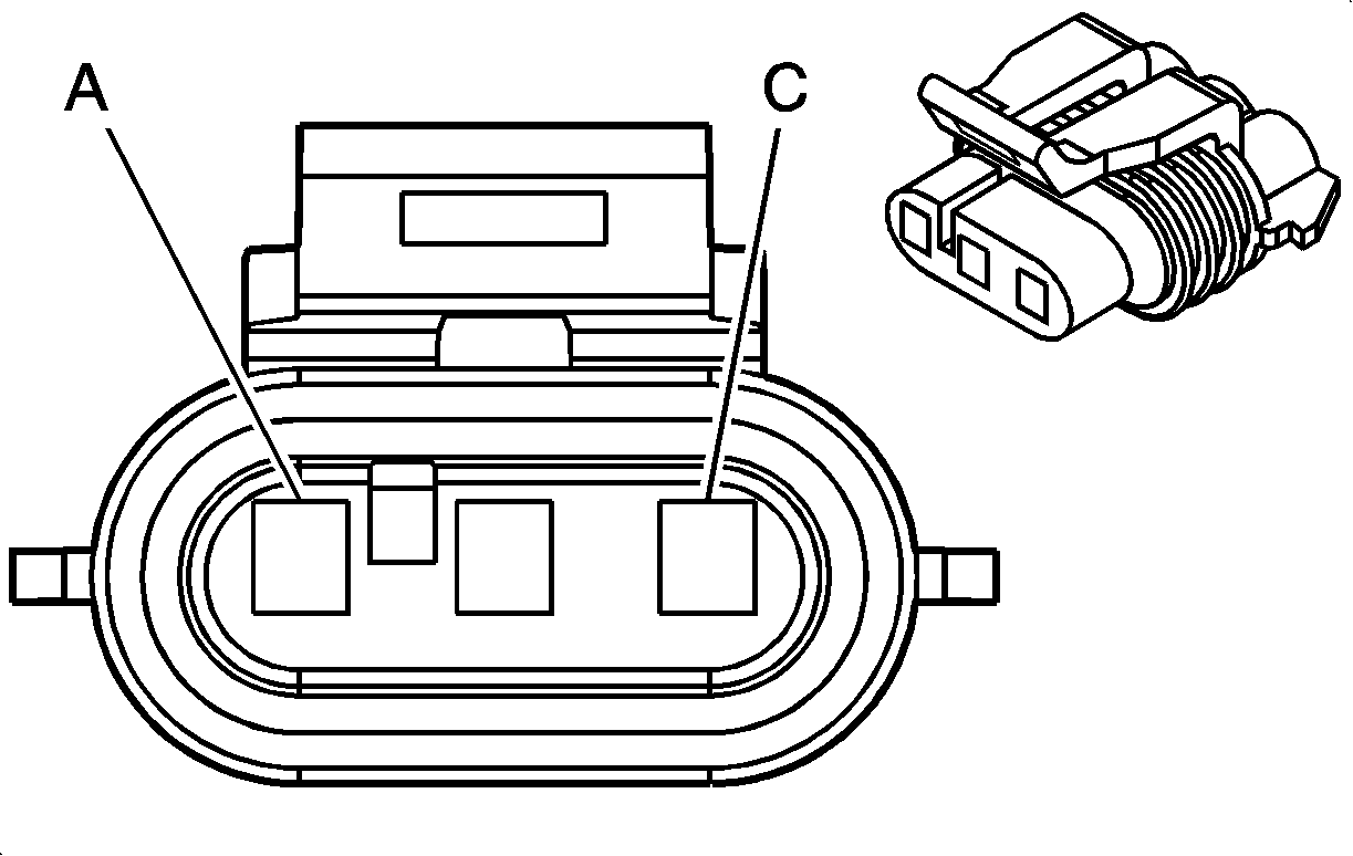
| |||||||
|---|---|---|---|---|---|---|---|
Connector Part Information |
| ||||||
Pin | Wire Color | Circuit No. | Function | ||||
A | L-BU | 406 | Ignition Coil (IC) Timing Control (1 and 4) | ||||
B | PK | 739 | Ignition 1 Voltage | ||||
C | D-GN/WH | 423 | Ignition Coil (IC) Timing Control (2 and 3) | ||||
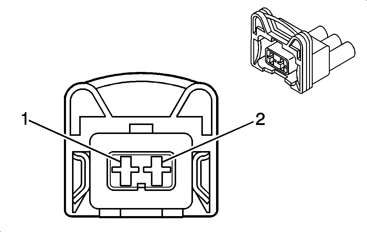
| |||||||
|---|---|---|---|---|---|---|---|
Connector Part Information |
| ||||||
Pin | Wire Color | Circuit No. | Function | ||||
1 | BK | 808 | Low Reference | ||||
2 | GY (BN) | 472 | Intake Air Temperature (IAT) Sensor Signal | ||||
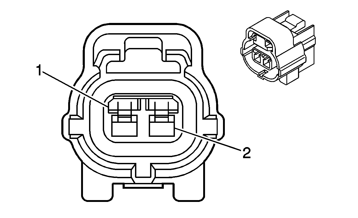
| |||||||
|---|---|---|---|---|---|---|---|
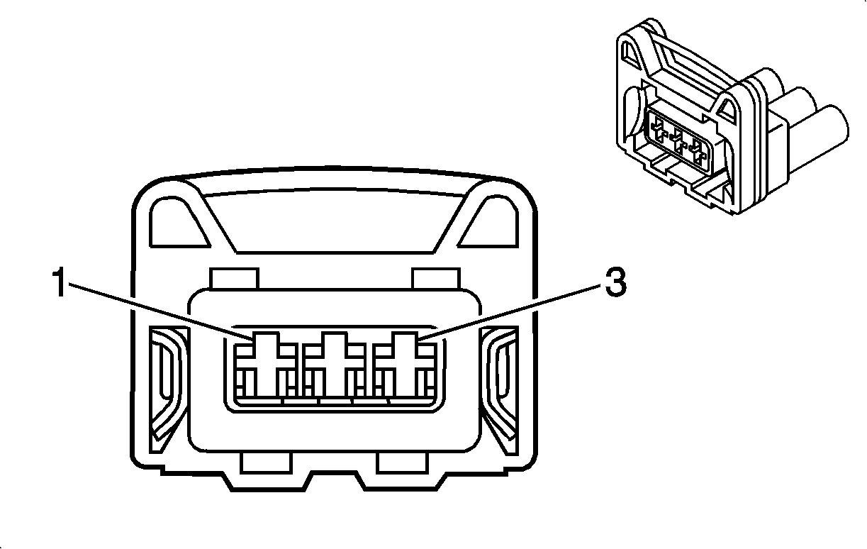
Connector Part Information |
| ||||||
Pin | Wire Color | Circuit No. | Function | ||||
1 | WH/BK | 962 | Intake Manifold Tuning Valve Solenoid Control | ||||
2 | PK/D-BU | 539 | Ignition 1 Voltage | ||||
| |||||||
|---|---|---|---|---|---|---|---|
Connector Part Information |
| ||||||
Pin | Wire Color | Circuit No. | Function | ||||
1 | YE/BK | 496 | Knock Sensor (KS) Signal | ||||
2 | D-BU/WH | 808 | Low Reference | ||||
3 | BK/WH | 51 | Ground | ||||

| |||||||
|---|---|---|---|---|---|---|---|
Connector Part Information |
| ||||||
Pin | Wire Color | Circuit No. | Function | ||||
1 | L-BU/BK | 1688 | 5-Volt Reference | ||||
2 | D-BU/WH (L-GN) | 432 | Manifold Absolute Pressure (MAP) Sensor Signal | ||||
3 | OG/BK | 469 | Low Reference | ||||

| |||||||
|---|---|---|---|---|---|---|---|
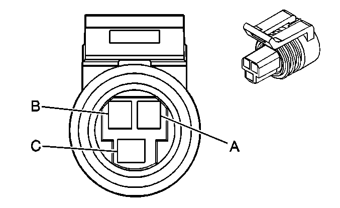
Connector Part Information |
| ||||||
Pin | Wire Color | Circuit No. | Function | ||||
A | GY | 605 | 5-Volt Reference | ||||
B | D-GN | 602 | Rough Road Sensor Signal | ||||
C | PU/WH | 632 | Low Reference | ||||
| |||||||
|---|---|---|---|---|---|---|---|
Connector Part Information |
| ||||||
Pin | Wire Color | Circuit No. | Function | ||||
A | D-GN/WH (D-GN/YE) | 416 | 5-Volt Reference | ||||
B | BK | 808 | Low Reference | ||||
C | GY (D-BU) | 417 | Throttle Position (TP) Sensor Signal | ||||
Engine Controls Connector End Views w/ Throttle Actuator Control
| Table 1: | Accelerator Pedal Position (APP) Sensor |
| Table 2: | Camshaft Position (CMP) Sensor |
| Table 3: | Crankshaft Position (CKP) Sensor |
| Table 4: | Engine Coolant Temperature (ECT) Sensor |
| Table 5: | Evaporative Emission (EVAP) Canister Purge Solenoid Valve |
| Table 6: | Evaporative Emission (EVAP) Vent Solenoid |
| Table 7: | Exhaust Gas Recirculation (EGR) Valve |
| Table 8: | Fuel Injector 1 |
| Table 9: | Fuel Injector 2 |
| Table 10: | Fuel Injector 3 |
| Table 11: | Fuel Injector 4 |
| Table 12: | Fuel Pump/Sender |
| Table 13: | Fuel Tank Pressure Sensor |
| Table 14: | Heated Oxygen Sensor (HO2S) 1 |
| Table 15: | Heated Oxygen Sensor (HO2S) 2 |
| Table 16: | Ignition Coil (IC) Module |
| Table 17: | Intake Air Temperature (IAT) Sensor |
| Table 18: | Knock Sensor (KS) |
| Table 19: | Manifold Absolute Pressure (MAP) Sensor |
| Table 20: | Rough Road Sensor (w/o ABS) |
| Table 21: | Throttle Body Assembly |
| |||||||
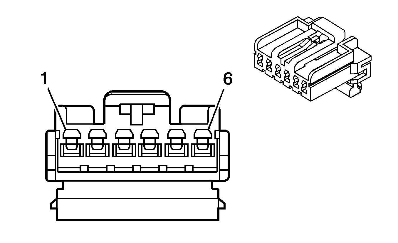
|---|---|---|---|---|---|---|---|
Connector Part Information |
| ||||||
Pin | Wire Color | Circuit No. | Function | ||||
1 | WH | 791 | APP Sensor 2 Signal | ||||
2 | PU | 1550 | Low Reference | ||||
3 | D-BU | 790 | APP Sensor 1 Signal | ||||
4 | L-BU | 1450 | Low Reference | ||||
5 | BN | 488 | 5 Volt Reference 1 | ||||
6 | BN/BK | 543 | 5 Volt Reference 2 | ||||

| |||||||
|---|---|---|---|---|---|---|---|
Connector Part Information |
| ||||||
Pin | Wire Color | Circuit No. | Function | ||||
1 | PK/BK | 1846 | Ignition 1 Voltage | ||||
2 | BK/WH | 251 | Ground | ||||
3 | PU | 633 | Camshaft Position (CMP) Sensor Signal | ||||

| |||||||
|---|---|---|---|---|---|---|---|
Connector Part Information |
| ||||||
Pin | Wire Color | Circuit No. | Function | ||||
1 | D-BU/WH | 1869 | Crankshaft Position (CKP) Sensor Signal | ||||
2 | YE/BK | 1868 | Low Reference | ||||
3 | BK/WH | 51 | Ground | ||||

| |||||||
|---|---|---|---|---|---|---|---|
Connector Part Information |
| ||||||
Pin | Wire Color | Circuit No. | Function | ||||
A | L-GN | 410 | Engine Coolant Temperature (ECT) Sensor Signal | ||||
B | BK | 808 | Low Reference | ||||

| |||||||
|---|---|---|---|---|---|---|---|
Connector Part Information |
| ||||||
Pin | Wire Color | Circuit No. | Function | ||||
A | PK/BK | 1846 | Ignition 1 Voltage | ||||
B | WH | 428 | Evaporative Emission (EVAP) Canister Purge Solenoid Control | ||||

| |||||||
|---|---|---|---|---|---|---|---|
Connector Part Information |
| ||||||
Pin | Wire Color | Circuit No. | Function | ||||
1 | L-BU/PU | 1986 | Evaporative Emission (EVAP) Canister Vent Solenoid Control | ||||
2 | PK/BK | 1846 | Ignition 1 Voltage | ||||

| |||||||
|---|---|---|---|---|---|---|---|
Connector Part Information |
| ||||||
Pin | Wire Color | Circuit No. | Function | ||||
A | D-GN | 435 | Exhaust Gas Recirulation (EGR) Solenoid Low Control | ||||
B | OG/BK | 469 | Low Reference | ||||
C | WH | 1456 | Exhaust Gas Recirulation (EGR) Valve Position Signal | ||||
D | L-BU/BK | 1688 | 5-Volt Reference | ||||
E | PK | 120 | Supply Voltage | ||||

| |||||||
|---|---|---|---|---|---|---|---|
Connector Part Information |
| ||||||
Pin | Wire Color | Circuit No. | Function | ||||
A | PK | 139 | Ignition 1 Voltage | ||||
B | YE/BU | 1744 | Fuel Injector 1 Control | ||||

| |||||||
|---|---|---|---|---|---|---|---|
Connector Part Information |
| ||||||
Pin | Wire Color | Circuit No. | Function | ||||
A | PK | 139 | Ignition 1 Voltage | ||||
B | BN/WH | 1745 | Fuel Injector 2 Control | ||||

| |||||||
|---|---|---|---|---|---|---|---|
Connector Part Information |
| ||||||
Pin | Wire Color | Circuit No. | Function | ||||
A | PK | 139 | Ignition 1 Voltage | ||||
B | D-GN/BK | 1746 | Fuel Injector 3 Control | ||||

| |||||||
|---|---|---|---|---|---|---|---|
Connector Part Information |
| ||||||
Pin | Wire Color | Circuit No. | Function | ||||
A | PK | 139 | Ignition 1 Voltage | ||||
B | D-GN/WH | 844 | Fuel Injector 4 Control | ||||

| |||||||
|---|---|---|---|---|---|---|---|
Connector Part Information |
| ||||||
Pin | Wire Color | Circuit No. | Function | ||||
1 | D-BU | 1936 | Fuel Level Sensor Signal | ||||
2 | BK | 1250 | Ground | ||||
3 | GY | 120 | Fuel Pump Supply Voltage | ||||
4 | BK | 1250 | Ground | ||||
5 | PU | 172 | Low Fuel Indicator Control | ||||
6 | PU/BK | 632 | Low Reference | ||||

| |||||||
|---|---|---|---|---|---|---|---|
Connector Part Information |
| ||||||
Pin | Wire Color | Circuit No. | Function | ||||
1 | BK/WH | 632 | Low Reference | ||||
2 | D-GN | 890 | Fuel Tank Pressure Sensor Signal | ||||
3 | GY | 605 | 5-Volt Reference | ||||

| |||||||
|---|---|---|---|---|---|---|---|
Connector Part Information |
| ||||||
Pin | Wire Color | Circuit No. | Function | ||||
1 | D-GN/RD | 1665 | Heated Oxygen Sensor (HO2S) 1 Low Reference | ||||
2 | PK/BK | 1846 | Ignition 1 Voltage | ||||
3 | GY | 1653 | Heated Oxygen Sensor (HO2S) 1 Signal | ||||
4 | BN/WH | 1669 | Heated Oxygen Sensor (HO2S) 1 Heater Control | ||||

| |||||||
|---|---|---|---|---|---|---|---|
Connector Part Information |
| ||||||
Pin | Wire Color | Circuit No. | Function | ||||
1 | PU | 1670 | Heated Oxygen Sensor (HO2S) 2 Signal | ||||
2 | PK/BK | 1846 | Ignition 1 Voltage | ||||
3 | L-GN | 413 | Low Reference | ||||
4 | BN/BK | 1671 | Heated Oxygen Sensor (HO2S) 2 Heater Control | ||||

| |||||||
|---|---|---|---|---|---|---|---|
Connector Part Information |
| ||||||
Pin | Wire Color | Circuit No. | Function | ||||
A | L-BU | 406 | Ignition Coil Control (1 and 4) | ||||
B | PK/BK | 739 | Ignition 1 Voltage | ||||
C | D-GN/WH | 423 | Ignition Coil Control (2 and 3) | ||||

| |||||||
|---|---|---|---|---|---|---|---|
Connector Part Information |
| ||||||
Pin | Wire Color | Circuit No. | Function | ||||
1 | BK | 808 | Low Reference | ||||
2 | GY | 472 | Intake Air Temperature (IAT) Sensor Signal | ||||

| |||||||
|---|---|---|---|---|---|---|---|
Connector Part Information |
| ||||||
Pin | Wire Color | Circuit No. | Function | ||||
1 | YE/BK | 496 | Knock Sensor (KS) Signal | ||||
2 | D-BU/WH | 808 | Low Reference | ||||

| |||||||
|---|---|---|---|---|---|---|---|
Connector Part Information |
| ||||||
Pin | Wire Color | Circuit No. | Function | ||||
1 | L-BU/BK | 1688 | 5-Volt Reference | ||||
2 | D-BU/WH | 432 | Manifold Absolute Pressure (MAP) Sensor Signal | ||||
3 | OG/BK | 469 | Low Reference | ||||

| |||||||
|---|---|---|---|---|---|---|---|
Connector Part Information |
| ||||||
Pin | Wire Color | Circuit No. | Function | ||||
A | GY | 605 | 5-Volt Reference | ||||
B | D-GN | 602 | Rough Road Sensor Signal | ||||
C | PU/WH | 632 | Low Reference | ||||
| |||||||
|---|---|---|---|---|---|---|---|
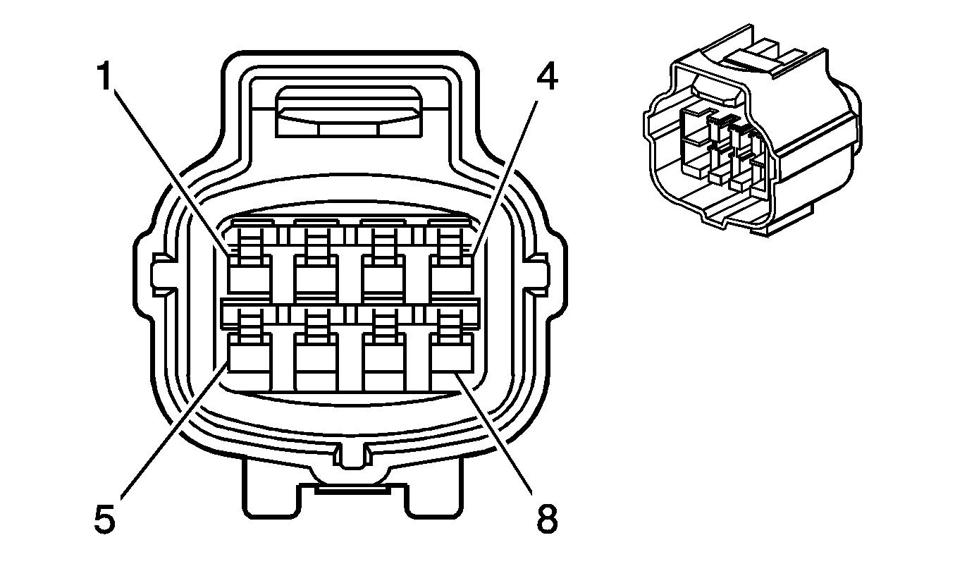
Connector Part Information |
| ||||||
Pin | Wire Color | Circuit No. | Function | ||||
1 | BN | 550 | Low Reference | ||||
2 | D-GN/WH | 417 | Throttle Position (TP) Sensor 1 Signal | ||||
3 | GY | 534 | Throttle Position (TP) Sensor 2 Signal | ||||
4 | D-BU/YE | 474 | 5-Volt Reference | ||||
5 | D-BU/RD | 426 | TAC Motor 1 Control | ||||
6-7 | -- | -- | Not Used | ||||
8 | L-BU/WH | 425 | TAC Motor 2 Control | ||||
