For 1990-2009 cars only
Disabling Procedure
- Turn the steering wheel so that the vehicle wheels are pointing straight ahead.
- Remove the key from the ignition switch.
- Remove the F1 fuse.
- Remove the knee bolster. Refer to Knee Bolster Replacement .
- Remove the following parts:
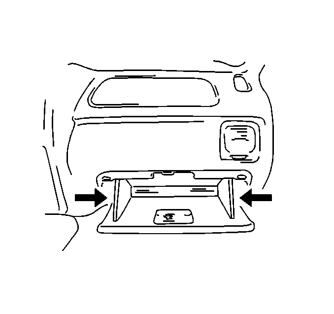
- Remove the glove box. Refer to Instrument Panel Storage Compartment Replacement .
- Remove the screws and the glove box housing.
- Remove the CPA and the yellow 2-way connector from the inflatable restraint instrument panel module (IPM) pigtail. Release then unlock the connector.
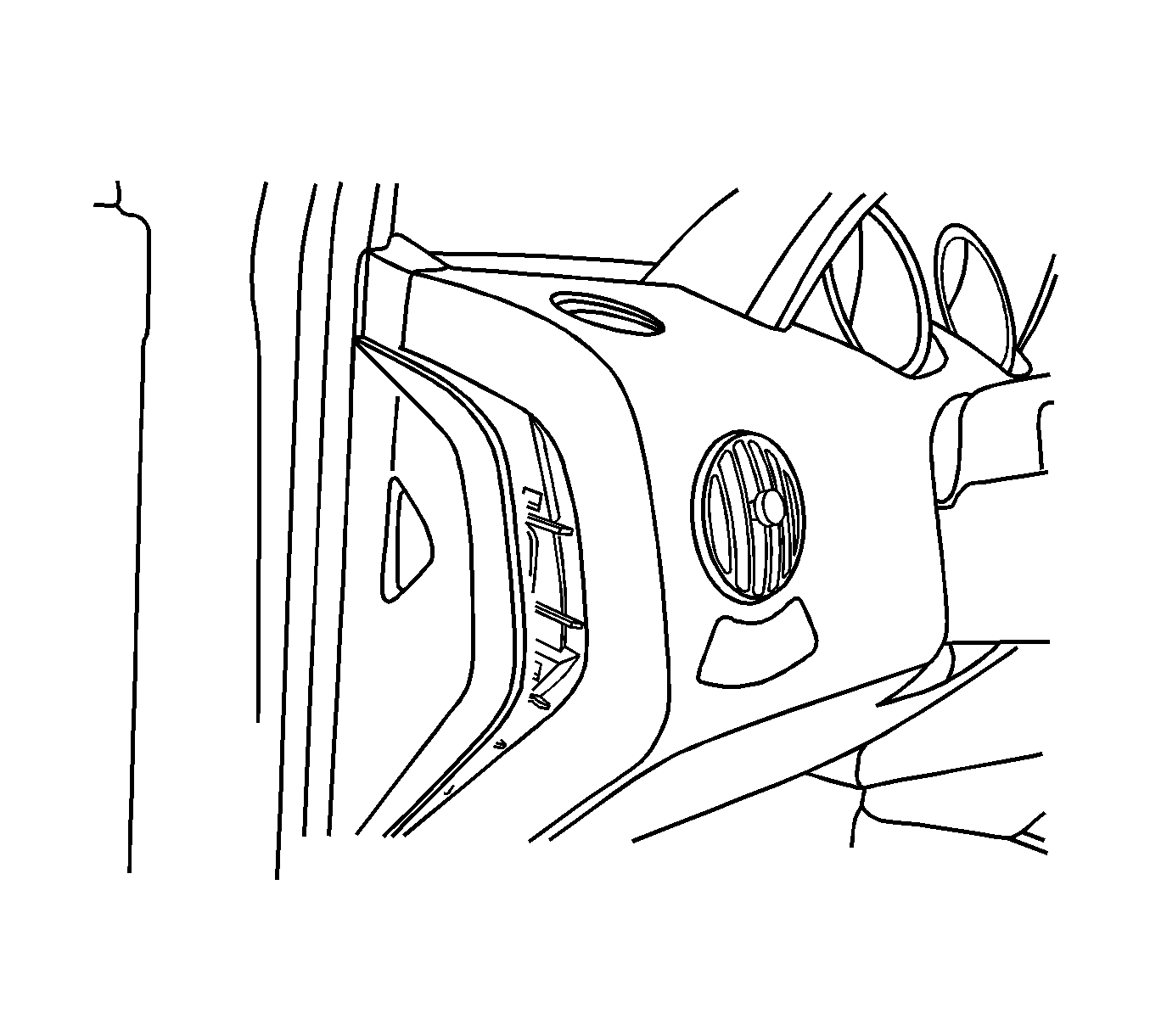
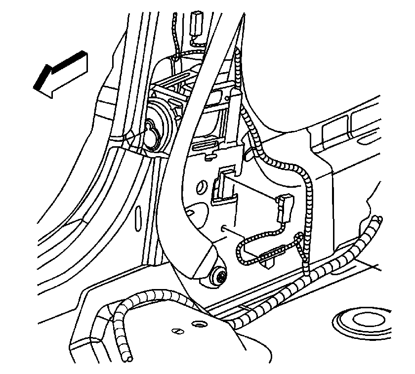
- Remove the right lower center pillar trim. Refer to Center Pillar Lower Trim Panel Replacement .
- Remove the CPA from the seat belt pretensioner - RF connector.
- Disconnect the seat belt pretensioner - RF connector from the vehicle harness connector.
- Remove the CPA from the side impact sensor - RF connector.
- Disconnect the side impact sensor - RF connector.
- Remove the left lower center pillar trim. Refer to Center Pillar Lower Trim Panel Replacement .
- Remove the CPA from the seat belt pretensioner - LF connector.
- Disconnect the seat belt pretensioner - LF connector from the vehicle harness connector.
- Remove the CPA from the side impact sensor - LF connector.
- Disconnect the side impact sensor - LF connector.
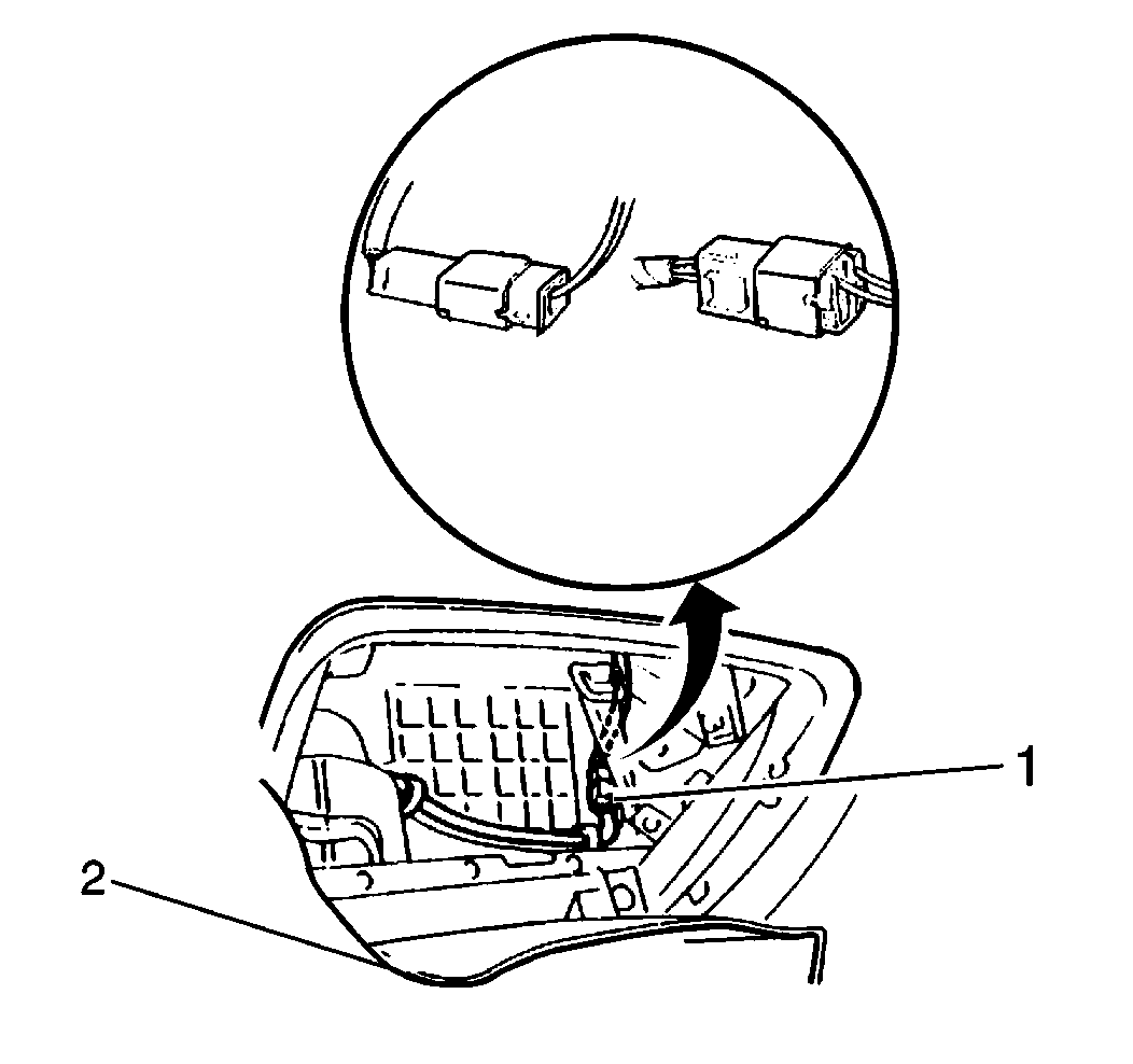
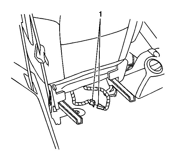
- Remove the CPA from the side impact module - LF connector (1) located under the driver seat.
- Disconnect the side impact module - LF connector (1).
- Remove the CPA from the side impact module - RF connector (1) located under the passenger seat.
- Disconnect the side impact module - RF connector (1).
Important: Perform this procedure in order to prevent deployment of the air bags from the reserve energy supply power.
Important: With the F1 fuse removed and the ignition switch is the ON position, the AIR BAG warning indicator illuminates. This is a normal operation, and does not indicate an SIR system malfunction.
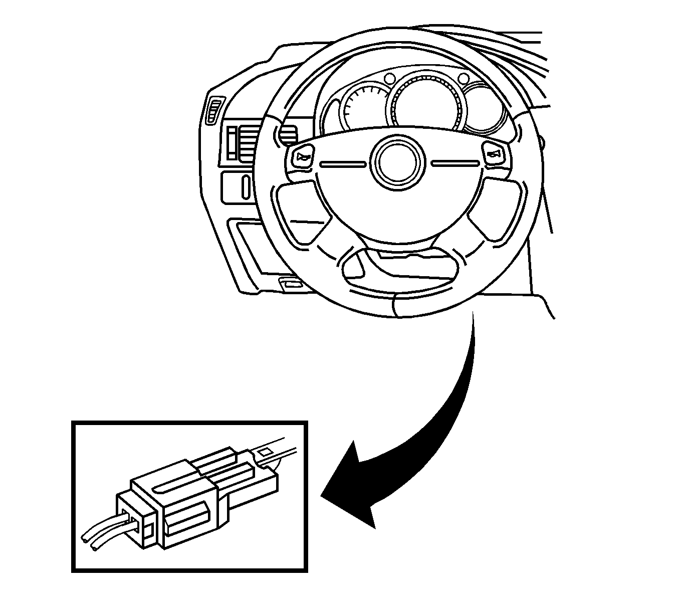
| • | The connector position assurance (CPA) |
| • | The yellow 2-way connector for the inflatable restraint steering wheel module--Release then unlock the connector. |
Enabling Procedure
- Remove the key from the ignition switch.
- Connect the side impact module - RF connector (1).
- Install the CPA to the side impact module - RF connector (1) located under the passenger seat.
- Connect the side impact module - LF connector (1) .
- Install the CPA to the side impact module - LF connector (1) located under the driver seat.
- Connect the seat belt pretensioner - LF connector from the vehicle harness connector.
- Install the CPA to the seat belt pretensioner - LF connector.
- Connect the side impact sensor - LF connector and install the CPA.
- Install the left lower center pillar trim. Refer to Center Pillar Lower Trim Panel Replacement .
- Connect the seat belt pretensioner- - RF connector from the vehicle harness connector.
- Install the CPA to the seat belt pretensioner - RF connector.
- Connect the side impact sensor - RF connector and install the CPA.
- Install the right lower center pillar trim. Refer to Center Pillar Lower Trim Panel Replacement .
- Install the yellow 2-way connector and install the CPA to the inflatable restraint IPM pigtail (1).
- Install the glove box housing and screws.
- Install the glove box. Refer to Instrument Panel Storage Compartment Replacement .
- Install the yellow 2-way connector (1) and the CPA (2) for the inflatable restraint steering wheel module. Also install the steering wheel side cap.
- Install the knee bolster. Refer to Knee Bolster Replacement .
- Install the F1 fuse.
- Staying well away from both air bags, turn the ignition switch to the ON position. Verify that the AIR BAG warning indicator flashes 7 times and then stays OFF. If the AIR BAG warning indicator does not operate as described, refer to Diagnostic System Check - Vehicle .


