For 1990-2009 cars only
Removal Procedure
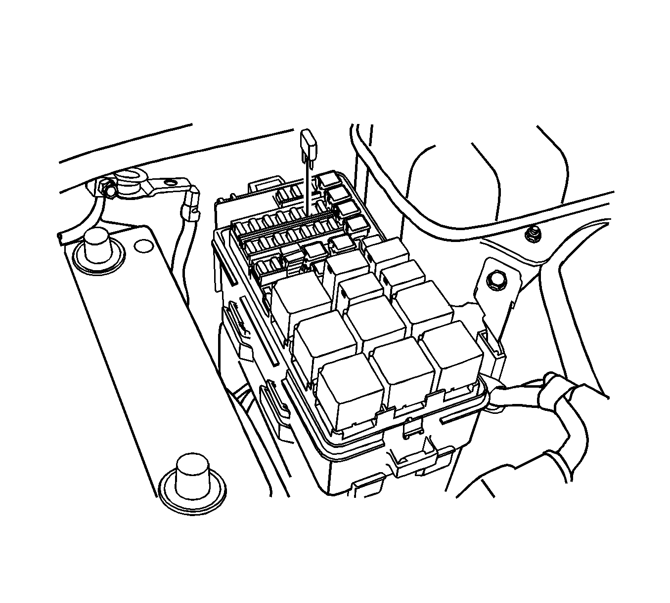
- Remove the fuel pump fuse.
- Start the engine. After it stalls, crank the engine for 10 seconds to rid the fuel system of fuel pressure.
- Disconnect the negative battery cable.
- Remove the air cleaner assembly.
- Drain the engine coolant. Refer to Cooling System Draining and Filling.
- Disconnect the engine coolant temperature (ECT) sensor electrical connector.
- Disconnect the purge solenoid valve connector.
- Disconnect the generator connector.
- Disconnect the A/C pressure switch connector.
- Disconnect the idle air control valve (IACV) connector.
- Disconnect the throttle position sensor (TPS) electrical connector.
- Disconnect the manifold air pressure (MAP) sensor electrical connector.
- Disconnect the oil pressure switch electrical connector.
- Disconnect the throttle body cable.
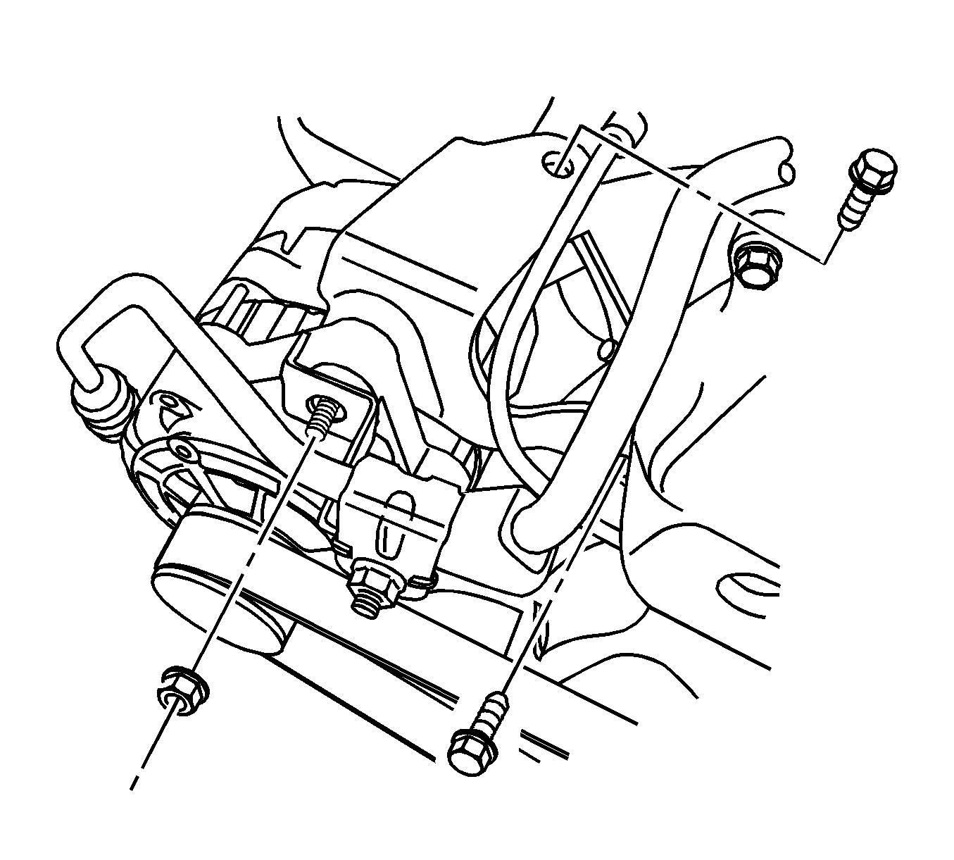
- Remove the generator upper bracket.
- Remove the fuel injector rail and the fuel injectors.
- Remove the engine control module (ECM).
- Remove the brake vacuum hoses from the intake manifold.
- Disconnect the VGIS valve electrical connector.
- Disconnect the knock sensor electrical connector.
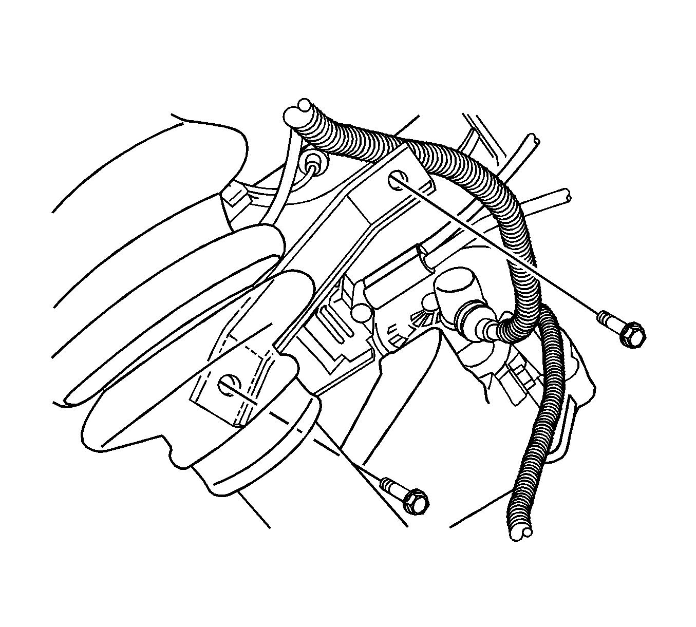
- Remove the intake manifold support bracket bolts.
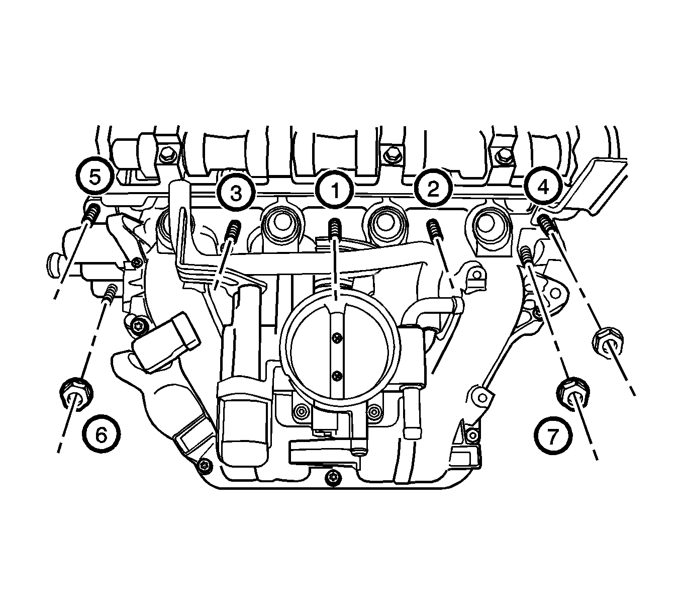
- Remove the intake manifold retaining nuts in the sequence shown.
- Remove the intake manifold and gasket.
- Clean the sealing surfaces of the intake manifold and the cylinder head.
Warning: Refer to Battery Disconnect Warning in the Preface section.
Warning: Refer to Safety Glasses Warning in the Preface section.
Installation Procedure
- Install the new intake manifold gasket and intake manifold.
- Install the intake manifold support bracket bolts.
- Connect the knock sensor electrical connector.
- Connect the VGIS valve electrical connector.
- Install the brake vacuum hoses from the intake manifold.
- Install the engine control module (ECM).
- Install the fuel injector rail and the fuel injectors.
- Install the generator upper bracket.
- Connect the throttle body cable.
- Connect the oil pressure switch electrical connector.
- Connect the manifold air pressure (MAP) sensor electrical connector.
- Connect the throttle position sensor (TPS) electrical connector.
- Connect the idle air control valve (IACV) connector.
- Connect the A/C pressure switch connector.
- Connect the generator connector.
- Connect the purge solenoid valve connector.
- Connect the engine coolant temperature (ECT) sensor electrical connector.
- Refill the engine coolant. Refer to Cooling System Draining and Filling.
- Install the air cleaner assembly.
- Connect the negative battery cable.
- Install the fuel pump fuse.
Caution: Refer to Fastener Caution in the Preface section.
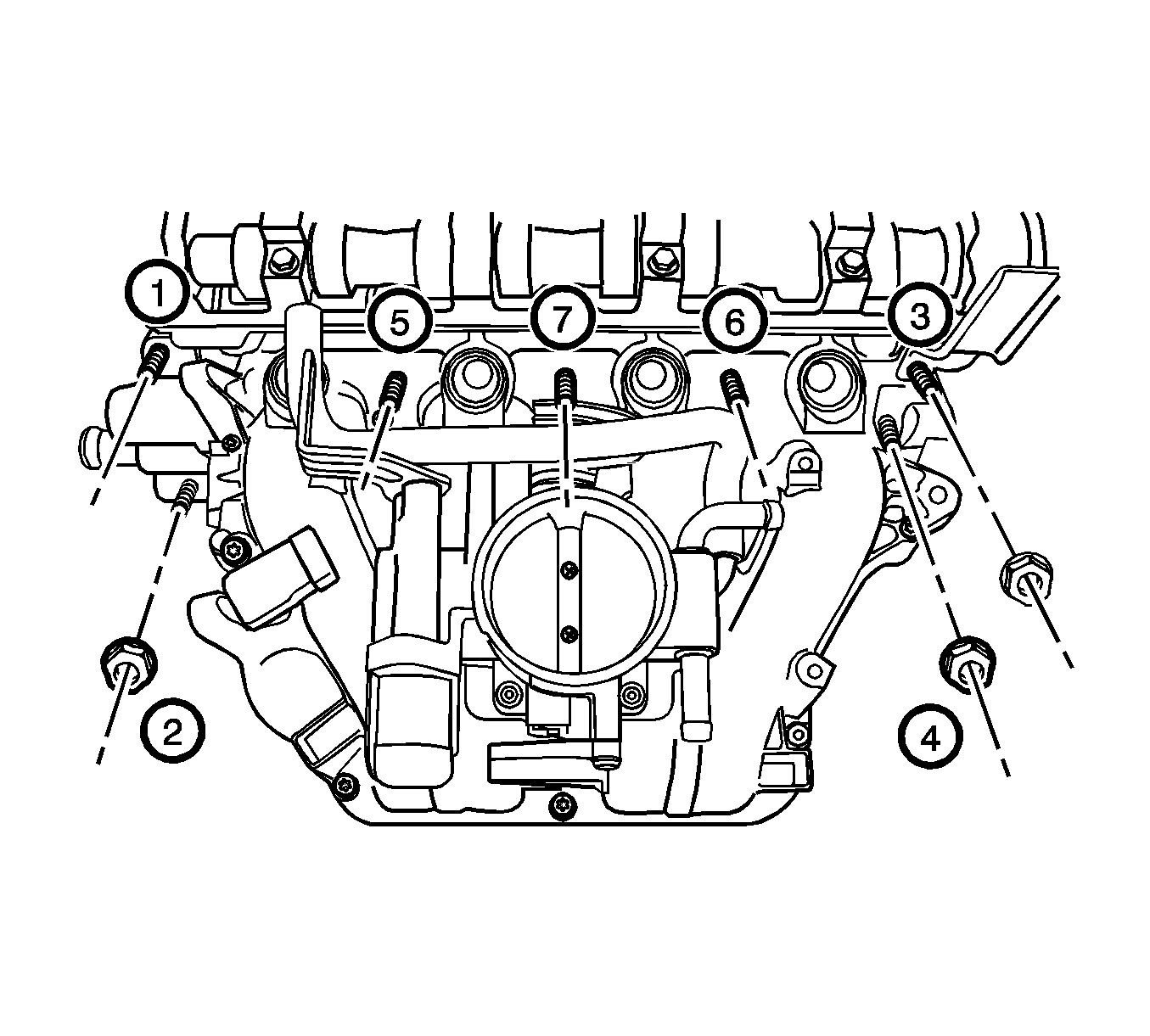
Tighten
Tighten the intake manifold bolts and nuts to 30 N·m (22 lb ft).

Tighten
Tighten the intake manifold support bracket upper bolt to 25 N·m (18 lb ft).
Tighten
Tighten the intake manifold support bracket lower bolt to 45 N·m (33 lb ft).

Tighten
Tighten the generator upper bracket bolts to 25 N·m (18 lb ft).
Warning: Refer to Safety Glasses Warning in the Preface section.
Warning: Refer to Battery Disconnect Warning in the Preface section.

