Removal Procedure
- Relieve the fuel system pressure. Refer to Fuel Pressure Relief.
- Disconnect the negative battery cable.
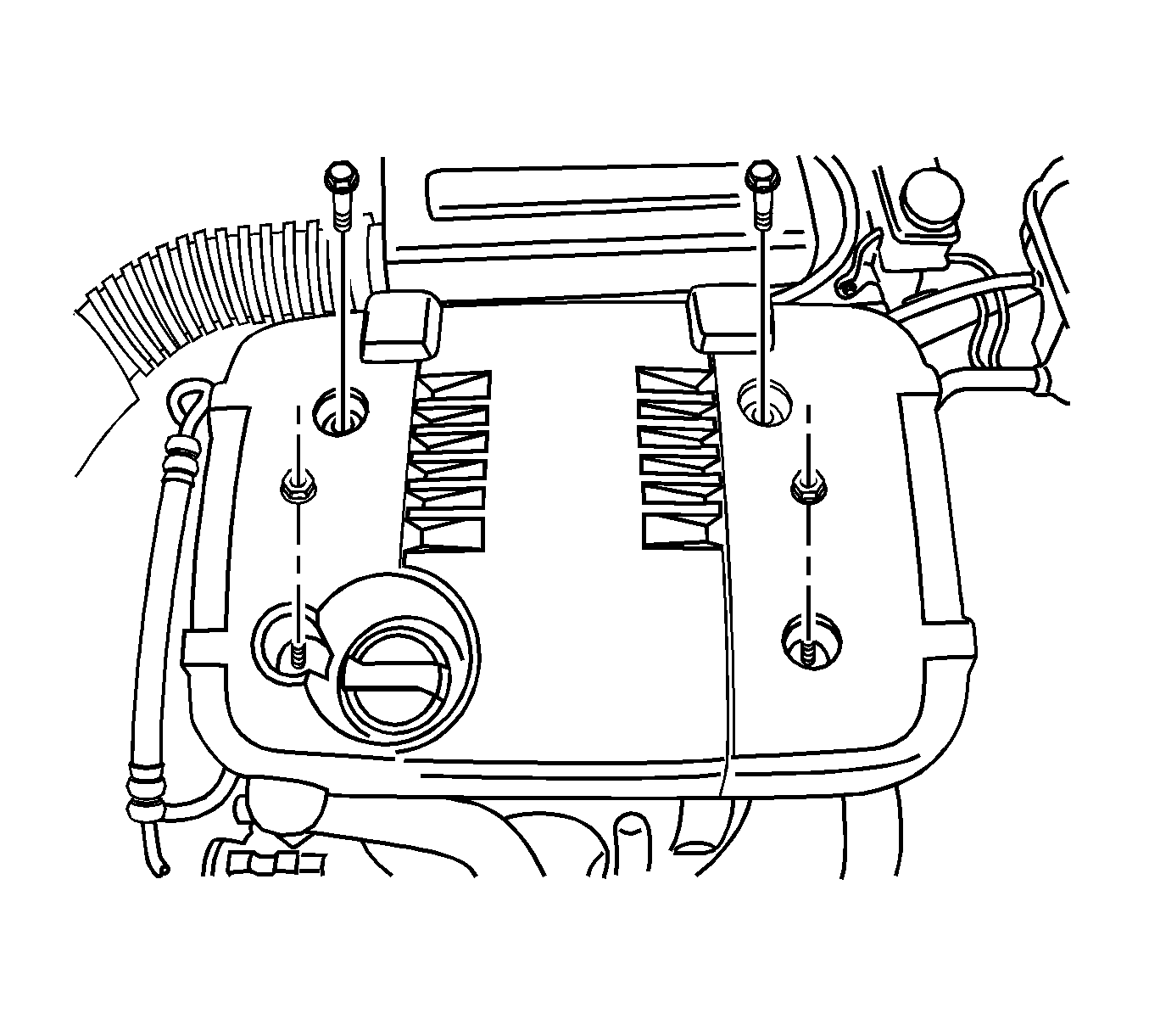
- Remove engine cover.
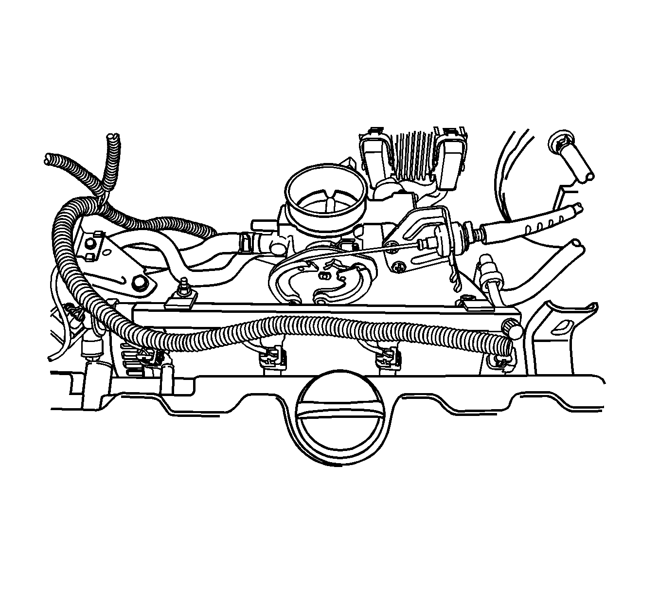
- Disconnect the intake air temperature (IAT) sensor connector.
- Disconnect the breather hose from the valve cover.
- Disconnect the fuel feed line at the fuel rail.
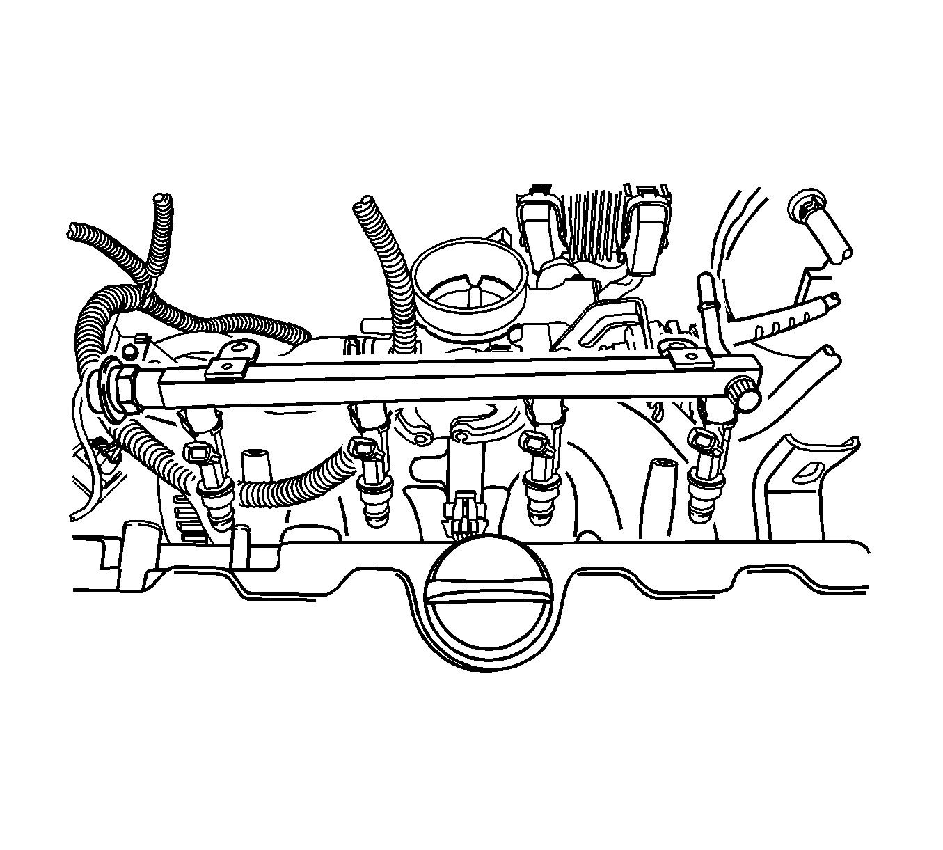
- Remove the fuel rail retaining bolts.
- Remove the fuel rail with the injectors attached.
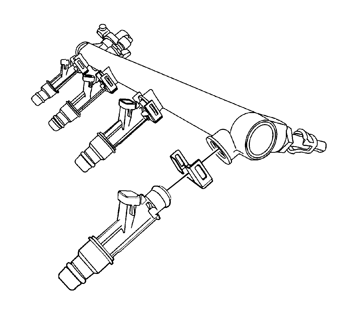
- Remove the fuel injector retainer clips.
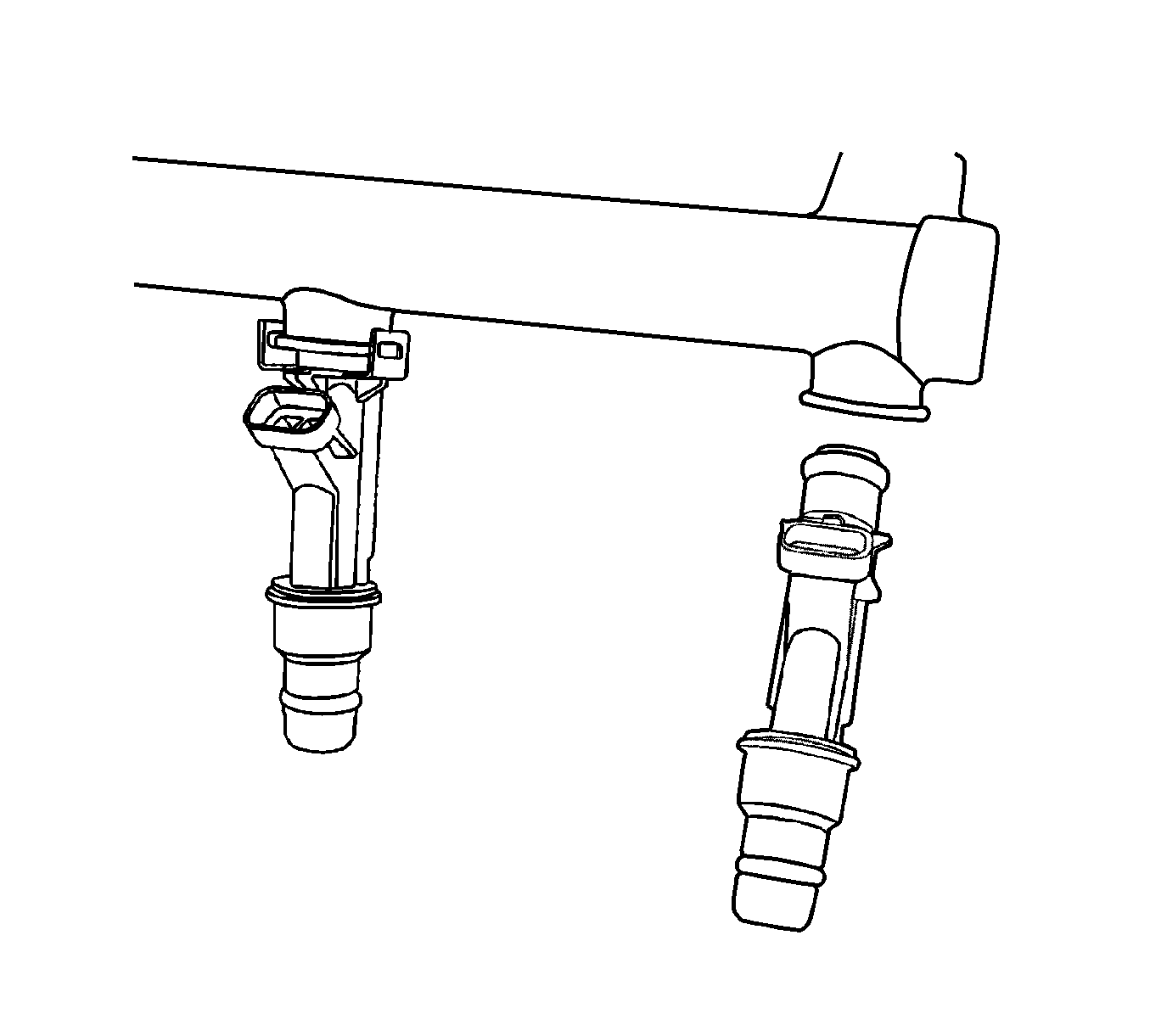
- Remove the fuel injectors by pulling them down and out.
- Discard the fuel injector O-rings.
Warning: Refer to Relieving Fuel Pressure Warning in the Preface section.
Warning: Relieve the fuel system pressure before servicing fuel system components in order to reduce the risk of fire and personal injury.
After relieving the system pressure, a small amount of fuel may be released when servicing the fuel lines or connections. In order to reduce the chance of personal injury, cover the regulator and the fuel line fittings with a shop towel before disconnecting. This will catch any fuel that may leak out. Place the towel in an approved container when the disconnection is complete.Warning: Refer to Battery Disconnect Warning in the Preface section.
Caution:
• Use care when servicing the fuel system components, especially the fuel injector electrical connectors, the fuel injector tips, and the injector O-rings. Plug the inlet and the outlet ports of the fuel rail in order to prevent contamination. • Do not use compressed air to clean the fuel rail assembly as this may damage the fuel rail components. • Do not immerse the fuel rail assembly in a solvent bath in order to prevent damage to the fuel rail assembly.
Note: If an injector becomes separated from the rail and remains in the cylinder head, replace the injector O-ring seals and the retaining clip.
Installation Procedure
- Lubricate the new fuel injector O-rings with engine oil. Install the new O-rings on the fuel injectors.
- Install the fuel injectors into the fuel rail sockets with the fuel injector terminals facing outward.
- Install the fuel injector retaining clips onto the fuel injector and the fuel rail ledge.
- Make sure that the clips are parallel to the fuel injector harness connector.
- Install the fuel rail assembly into the cylinder head.
- Install the fuel rail retaining bolts and tighten to 12 N·m (10 lb in).
- Connect the fuel feed line to the fuel rail.
- Connect the fuel injector connectors. Rotate each fuel injector as required.
- Connect the PCV hose to the valve cover.
- Connect the breather hose to the valve cover.
- Connect the IAT sensor connector.
- Install engine cover.
- Connect the negative battery cable.
- Perform a leak check of the fuel rail and fuel injectors.
Note: Different injectors are calibrated for different flow rates. When ordering new fuel injectors, be certain to order the identical part number that is inscribed on the old injector.

Caution: Refer to Fastener Caution in the Preface section.

