For 1990-2009 cars only
Removal Procedure
- Disconnect the negative battery cable.
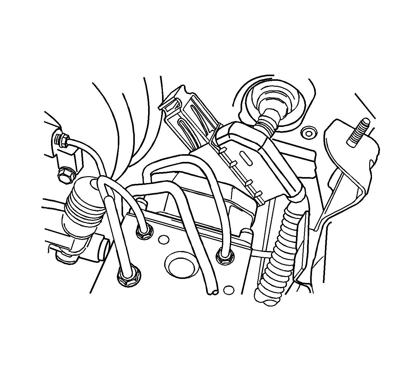
- Disconnect the 31-pin antilock brake system (ABS) wiring harness connector from its socket on the electronic brake control module (EBCM).
- Cover the connector and the socket with shop cloths to protect the components from brake fluid.
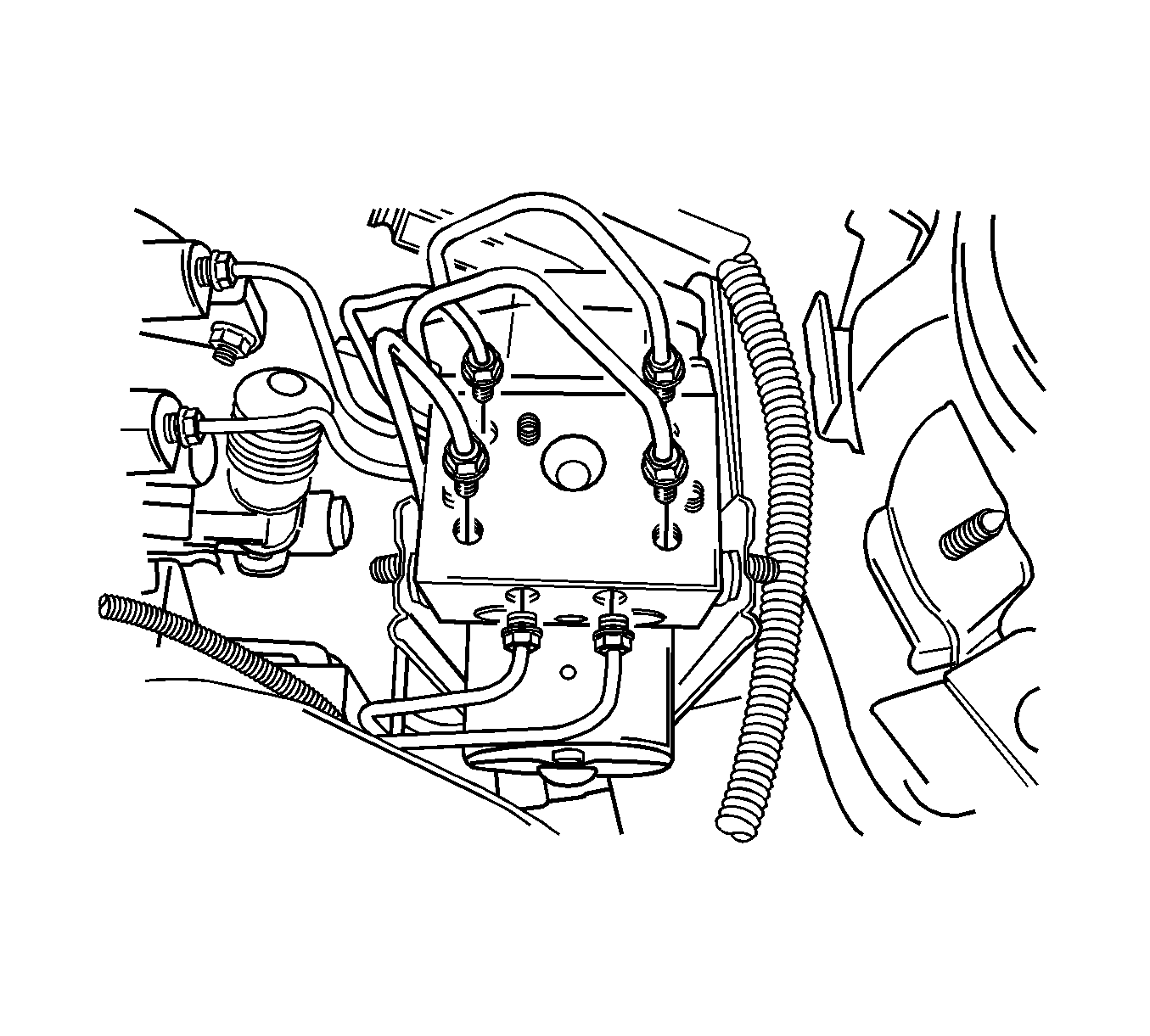
- Remove the brake pipes from the brake pressure modulator valve. You may have to loosen the brake pipe nuts on the master cylinder to allow for moving those pipes out of the way.
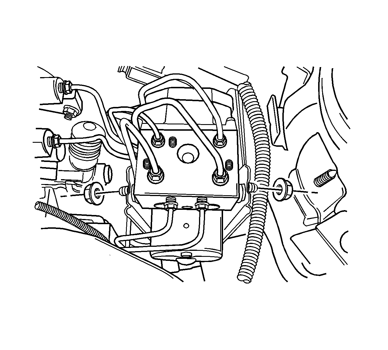
- Loosen the mounting nuts on the brake pressure modulator valve.
- Move the brake pipes aside far enough to allow for lifting the ABS unit out of the mounting bracket.
- Tighten the brake pipe nuts on the master cylinder to avoid leaking brake fluid.
- Cap the brake pipes.
Warning: Refer to Battery Disconnect Warning in the Preface section.


Installation Procedure
- Insert the ABS brake pressure modulator valve into the mounting bracket and install the nuts and tighten to 15 N·m (11 lb ft).
- Remove the screw plugs and install all of the hydraulic brake pipes and tighten to 22 N·m (16 lb ft).
- Connect the 31-pin wiring harness connector J1.
- Connect the negative battery cable.
- Bleed the hydraulic system. Refer to Hydraulic Brake System Bleeding.
- Refer to Control Module References for programming and setup information.
Caution: Refer to Fastener Caution in the Preface section.

