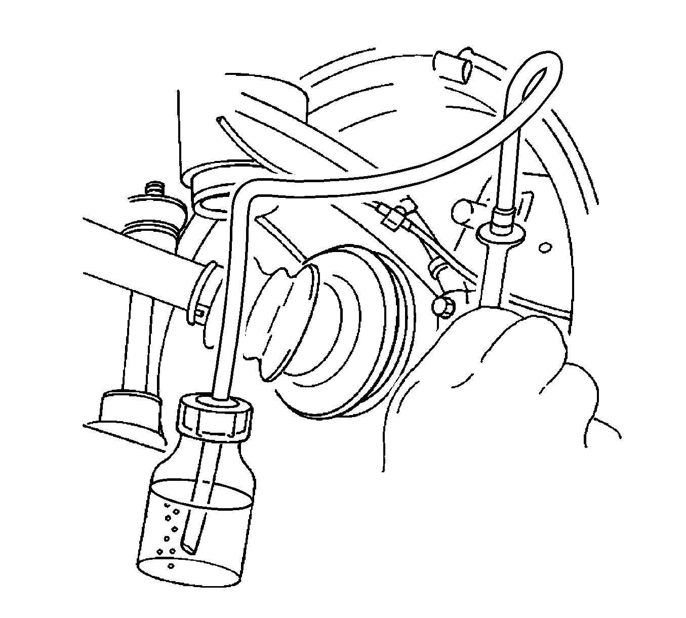
Hydraulic Brake System Bleeding ABS
- Disconnect the master cylinder electrical connector.
- Connect the bleeder with the adapter to the master cylinder reservoir.
- For vehicles with the antilock braking system (ABS), locate and remove the hydraulic modulator bleeder valves.
- Charge the bleeder ball to 140-172 kPa (20-25 psi).
- Connect the line to the adapter. Open the line valve.
- Raise and suitably support the vehicle. Refer to Lifting and Jacking the Vehicle.
- Attach the bleeder hose to the bleeder valve. Submerge the opposite end of the hose in a clean container partially filled with brake fluid.
- Open the bleeder valve ½-¾ turn and allow the fluid to flow until no air is seen in the fluid.
- Remove the master cylinder reservoir cap.
- Inspect the brake pedal for sponginess. Repeat the entire bleeding procedure to correct this condition.
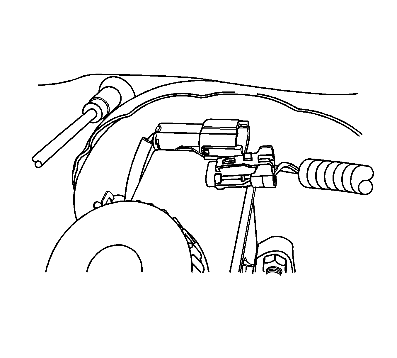
Caution: Pressure bleeding equipment must be of the diaphragm type. It must have a rubber diaphragm between the air supply and the brake fluid to prevent air, moisture, oil and other contaminants from entering the hydraulic system.
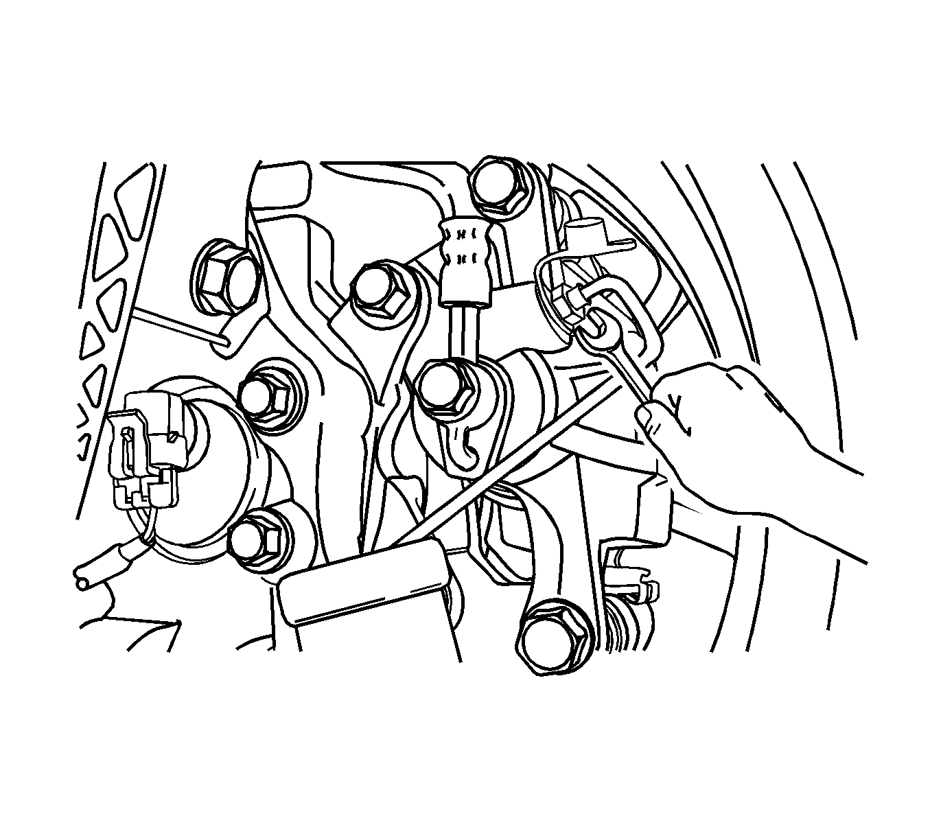
Note: The bleeding sequence is as follows: right rear, left front, left rear, and right front.
Caution: After the brake system bleeding procedure is complete, wrap a shop towel around the bleeder adapter and all hose connections before disconnecting. The brake reservoir may have residual pressure after the bleeding operation and failure to properly maintain the brake fluid may result in damage to components and painted surfaces.
Hydraulic Brake System Bleeding Manual
- Remove the booster reserve by applying the brakes several times with the engine OFF until all the reserve is depleted.
- Fill the master cylinder reservoir with brake fluid. Keep the master cylinder at least 1/2 full of fluid during the bleeding operation.
- Disconnect the front brake lines at the master cylinder.
- Allow the brake fluid to fill the master cylinder until it begins to flow from the front pipe connector port.
- Connect the front brake lines to the master cylinder and tighten to 16 N·m (12 lb ft).
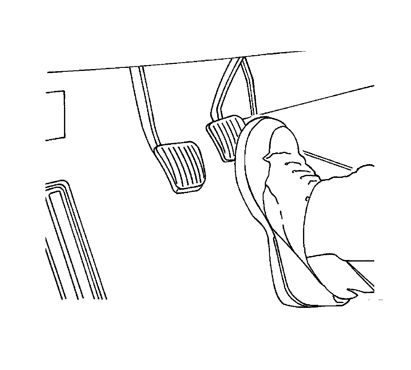
- Slowly push and hold the brake pedal one time.
- Loosen the front brake line at the master cylinder to purge air from the cylinder.
- Tighten the brake line as in step 5, and then release the brake pedal slowly. Wait 15 seconds before proceeding to the next step.
- Repeat the sequence, including the 15-second wait, until all the air is removed from the master cylinder bore.
- After all the air has been removed at the forward connections, bleed the master cylinder at the rear, cowl, connections in the same manner as with the front connections.
- Attach a transparent tube over the valve. Allow the tube to hang submerged in brake fluid in a transparent container.
- Slowly push and hold the brake pedal one time.
- Remove the bleeder valve dust cover and loosen the bleeder screw to purge the air from the cylinder.
- Install the bleeder screw and tighten to 8 N·m (71 lb in).
- Slowly release the brake pedal. Wait 15 seconds before proceeding with the next step.
- Repeat the sequence, including the 15-second wait, until all the air is removed. It may be necessary to repeat the sequence 10 or more times to remove all the air.
- Locate the front bleeder caps.
- Proceed to bleed the front brakes following the appropriate sequence, beginning with step 12.
- Inspect the brake pedal for sponginess. Repeat the entire bleeding procedure to correct this condition.
- Replace the bleeder valve dust cover.

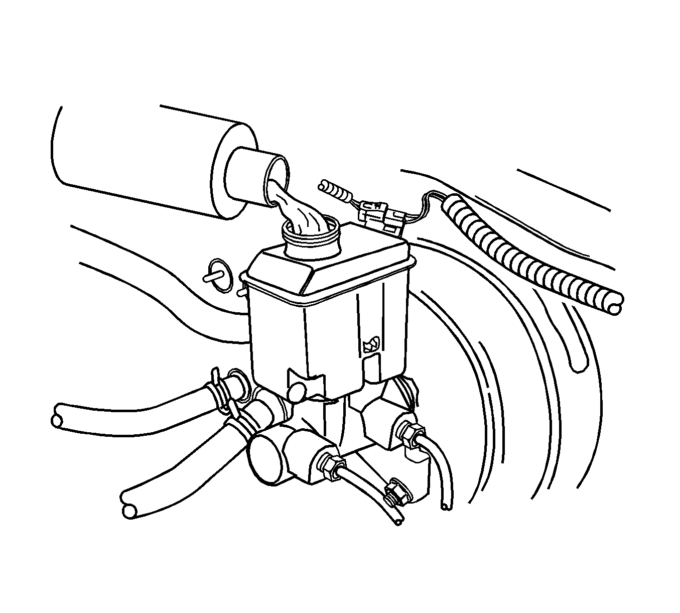
Note: If the master cylinder is known or suspected to have air in the bore, then it must be bled before any wheel cylinder or caliper is bled.
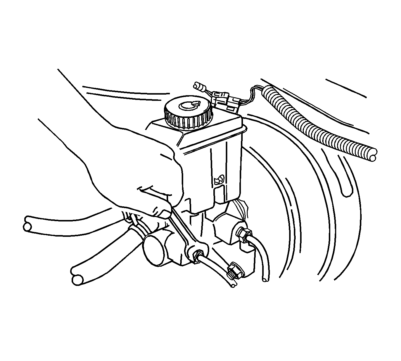
Caution: Refer to Fastener Caution in the Preface section.


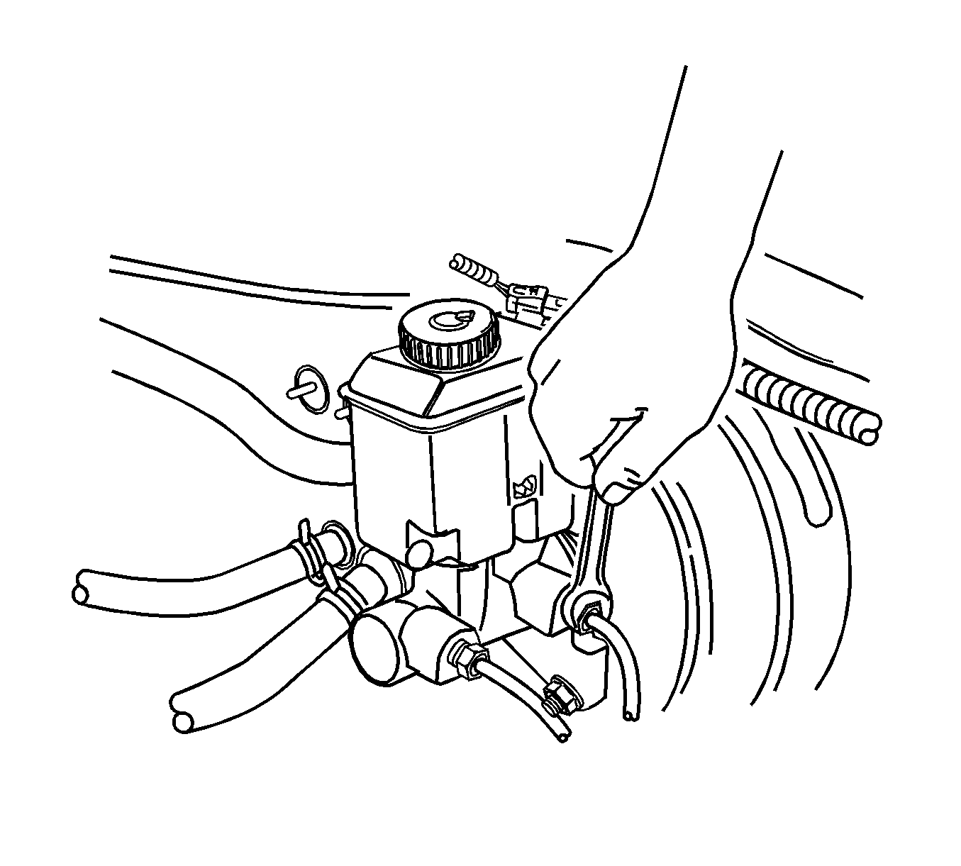
Caution: Avoid spilling brake fluid on any of the vehicle's painted surfaces, wiring, cables or electrical connectors. Brake fluid will damage paint and electrical connections. If any fluid is spilled on the vehicle, immediately flush the area with water to minimize the potential for damage.

Note: For vehicles equipped with a non-antilock braking system, the bleeding sequence is as follows: right rear, left rear, left front, and right front.
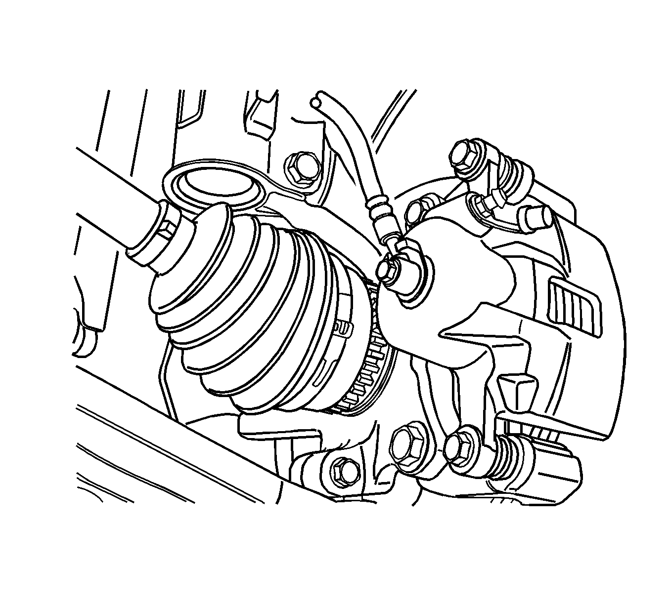
Note: Rapid pumping of the brake pedal pushes the master cylinder secondary piston down the bore in a manner that makes it difficult to bleed the system.
