Lower Control Arm Ball Joint Replacement for Chevrolet PJJ 2000
Removal Procedure
Tools Required
J 43828 Ball Joint Separator
- Raise and suitably support the vehicle. Refer to Lifting and Jacking the Vehiclein General Information.
- Remove the tire and wheel assemblies. Refer to Tire and Wheel Removal and Installationin Tires and Wheels.
- Remove the stabilizer shaft link. Refer to Stabilizer Shaft Link Replacement.
- Remove the wiring harness from the lower control arm.
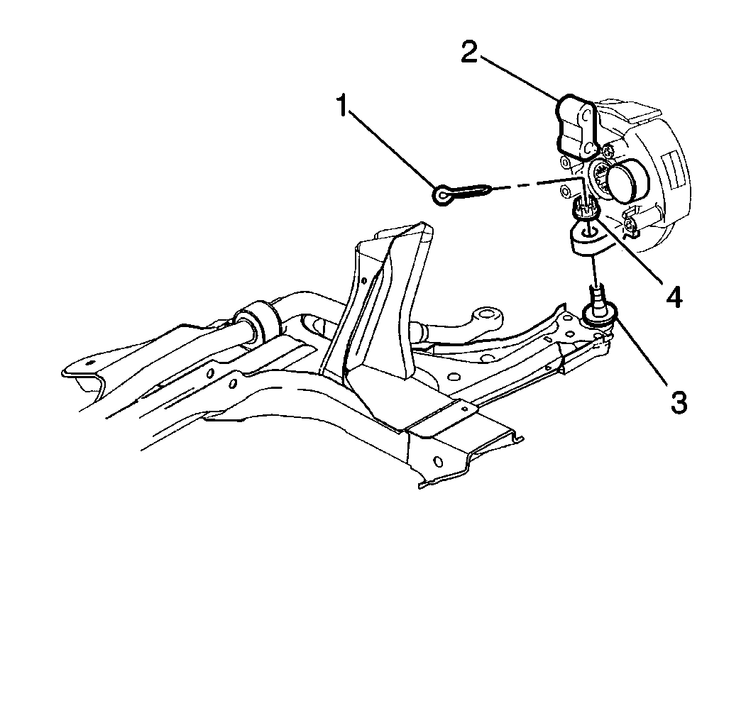
- Remove the cotter pin (1) from the ball joint (3).
- Remove the nut (4) from the ball joint (3).
- Remove the ball joint from the steering knuckle using the J 43828 Ball Joint Separator.
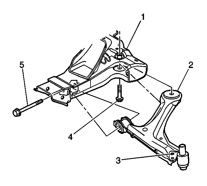
- Remove the lower control arm front (1) and rear (4) mounting bolts.
- Remove the lower control arm (1) from the vehicle and place in a vice.
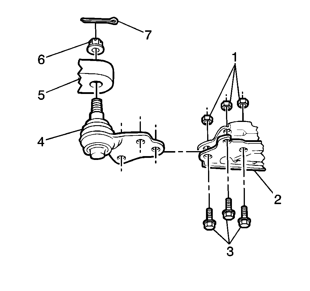
- Drill out the 3 rivets (3) retaining the ball joint to the lower control arm (2).
- Remove the ball joint (4) from the control arm (2).
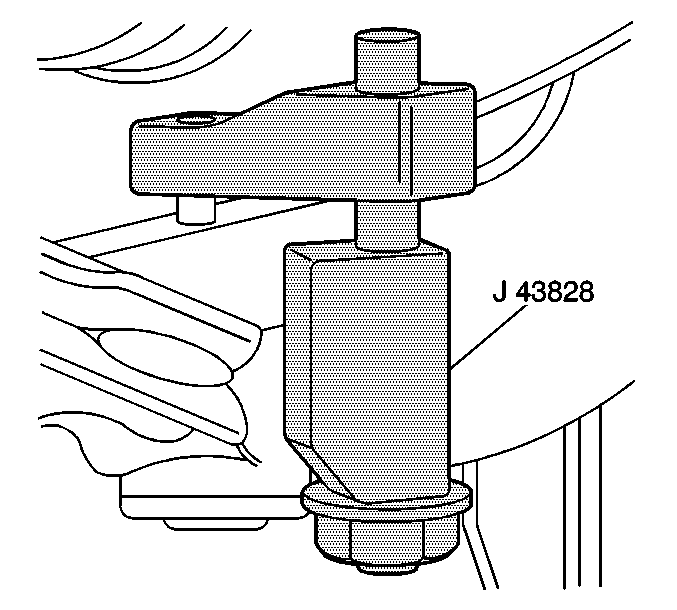
Notice: Use only the recommended tools for separating the ball joint from the knuckle. Failure to use the recommended tools may cause damage to the ball joint and seal.
Use a 3 mm (1/8 in) drill bit in order to make a pilot hole through the rivets.
Finish drilling the rivets with a 13 mm (½ in) drill bit.
Installation Procedure
- Install the ball joint (4) into the control arm (2).
- Install the 3 ball joint bolts (3) and the nuts (1). Follow the instructions in the ball joint kit. Tighten the ball joint bolts (3) according to the specifications in the instructions.
- Install the lower control arm (2) to the front suspension support (1)
- Install the lower control arm front (5) and rear (4) mounting bolts.
- Install the lower ball joint stud (3) to the steering knuckle (2).
- Install the ball joint stud (3) through the steering knuckle (2).
- Install the ball joint nut (4).
- Install the wiring harness to the lower control arm.
- Install the cotter pin (1).
- Install the stabilizer link to the lower control arm. Refer to Stabilizer Shaft Link Replacement.
- Install the tire and wheel assemblies. Refer to Tire and Wheel Removal and Installation in Tires and Wheels.
- Inspect the front wheel alignment. Refer to Wheel Alignment Specifications in Wheel Alignment.
Notice: Use the correct fastener in the correct location. Replacement fasteners must be the correct part number for that application. Fasteners requiring replacement or fasteners requiring the use of thread locking compound or sealant are identified in the service procedure. Do not use paints, lubricants, or corrosion inhibitors on fasteners or fastener joint surfaces unless specified. These coatings affect fastener torque and joint clamping force and may damage the fastener. Use the correct tightening sequence and specifications when installing fasteners in order to avoid damage to parts and systems.
Tighten
| • | Tighten the front bolt to 107 N·m (79 lb ft). |
| • | Tighten the rear bolt to 170 N·m (125 lb ft). |
Notice: Use the correct fastener in the correct location. Replacement fasteners must be the correct part number for that application. Fasteners requiring replacement or fasteners requiring the use of thread locking compound or sealant are identified in the service procedure. Do not use paints, lubricants, or corrosion inhibitors on fasteners or fastener joint surfaces unless specified. These coatings affect fastener torque and joint clamping force and may damage the fastener. Use the correct tightening sequence and specifications when installing fasteners in order to avoid damage to parts and systems.
Tighten
Tighten the ball joint nut to 55 N·m (41 lb ft)
minimum-65 N·m (50 lb ft) maximum to install
the cotter pin.
