Caution: Keep fingers and tools away from the opening in the starter
drive housing while performing the Starter No Load Test. The strong shifting
action of the solenoid could cause personal injury or damage as the drive
pinion moves into the cranking position and spins.
Notice: Do not allow the solenoid pull-in current to flow for more
than 15 seconds at a time. The windings can be damaged by overheating. Also,
the current draw readings will decrease as the windings heat up.
- Remove the starter motor from the vehicle. Refer to
Starter Motor Replacement
.

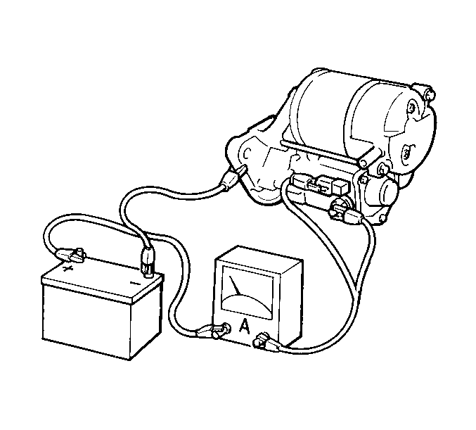
- Connect the test leads
from the battery and the ammeter to the starter motor assembly.
- Ensure that the following conditions are met:
| • | The starter motor runs smoothly. |
| • | The pinion extends quickly and completely. |
- Measure the starter motor current draw.
Starter Motor Current Draw
90 amperes or less at 11.5 volts
Evaluation
Low free speed and high current draw indicates the following conditions:
| | The following conditions may cause too much friction: |
| - | A bend in the armature that allows the armature to drag. |
| | Inspect for a shorted armature on a growler after disassembly. |
| • | Grounded armature or fields |
| | Inspect further after disassembly. |
Failure to operate and high current draw indicates the following conditions:
| • | A direct ground in the terminal or fields |
Failure to operate and low or no current draw indicates the following
conditions:
| | Inspect the open field circuit after disassembly by inspecting internal
connections. |
| | Inspect the commutator for badly burned bars after disassembly. |
| • | High insulation between the commutator bars |
| • | Other conditions that may prevent good contact between the brushes
and the commutator |
Low no-load speed and low current draw indicates the following conditions:
| • | High internal resistance due to poor connections |
| | Inspect the condition of the internal components after disassembly in
order to find an open field circuit. |
| | Inspect the commutator for badly burned bars after disassembly. |
| • | High insulation between the commutator bars or other conditions
which may prevent contact between the brushes and the commutator |
High free speed and high current draw indicate shorted fields.
| • | If you suspect shorted fields, replace the field coil assembly. |
| • | Use a growler in order to inspect for a shorted armature. |
Rated current draw and no-load speed indicate the normal condition of
the starter motor assembly.
If any of the above conditions are unsatisfactory, refer to
Starter Motor Overhaul
.
Starter Motor Pull-In, Hold-In and Pinion Return Testing
Notice: Do not allow the solenoid pull-in current to flow for more
than 15 seconds at a time. The windings can be damaged by overheating. Also,
the current draw readings will decrease as the windings heat up.

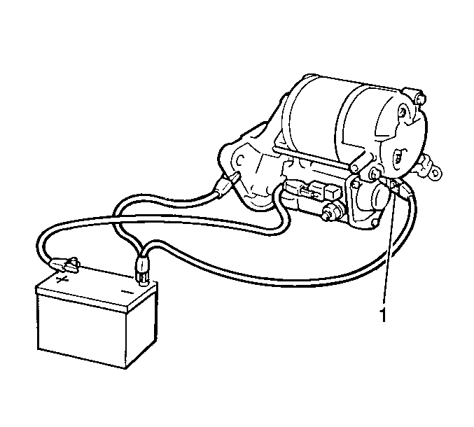
- Remove the field coil
lead wire from the solenoid terminal C (1).
- Install the test leads from the battery to the starter motor assembly.
- Ensure that the pinion extends quickly and completely to the energized
position (pull-in test).

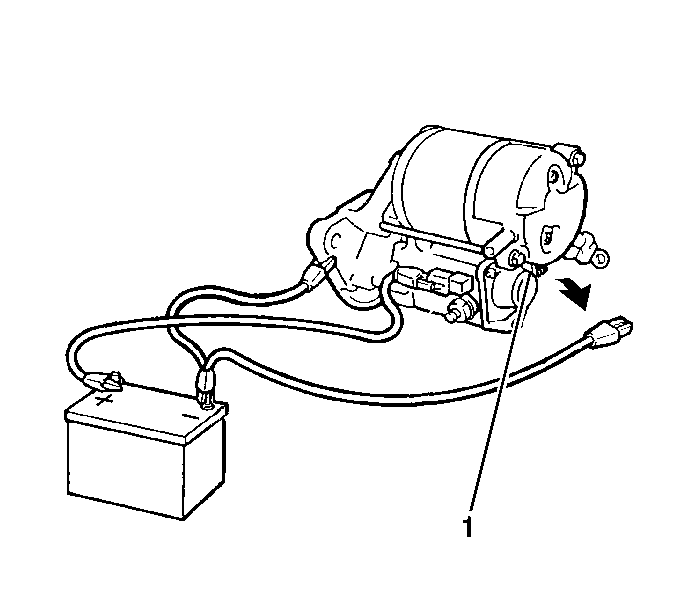
- Remove the negative (-)
lead from the solenoid terminal C (1).
- Verify that the pinion remains completely in the energized position
(hold-in test).

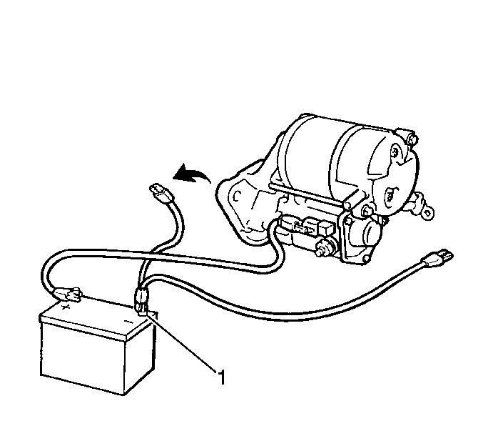
- Remove the negative (-)
lead from the drive housing.
- Ensure that the pinion returns quickly and completely to the de-energized
position (pinion return test).
- If the pinion does not return to the de-energized position, the
cause is most likely a faulty starter solenoid return spring. Replace the
starter solenoid.
- If any of the above tests are not satisfactory, replace the starter
solenoid. Refer to
Starter Motor Overhaul
.
- Install the field coil lead wire (1) to the solenoid terminal.
Notice: Use the correct fastener in the correct location. Replacement fasteners
must be the correct part number for that application. Fasteners requiring
replacement or fasteners requiring the use of thread locking compound or sealant
are identified in the service procedure. Do not use paints, lubricants, or
corrosion inhibitors on fasteners or fastener joint surfaces unless specified.
These coatings affect fastener torque and joint clamping force and may damage
the fastener. Use the correct tightening sequence and specifications when
installing fasteners in order to avoid damage to parts and systems.
Tighten
Tighten the nut to 6 N·m (52 lb in).
- Install the starter motor assembly onto the vehicle. Refer to
Starter Motor Replacement
.


