The cranking circuit consists of the battery , the starter motor , the ignition switch and related parts. All of these components are connected electrically. Refer to Starting and Charging Schematics and Starting System Check for electrical schematics and diagnostic procedures.
The starter solenoid windings are energized when the ignition switch is turned to the START position and the clutch pedal position (CPP) switch (manual transaxle) or the park/neutral position (PNP) switch (automatic transaxle) is closed. On manual transaxle equipped vehicles, the clutch pedal must be fully depressed to activate the clutch pedal position switch. The resulting plunger and pinion drive lever movement causes the drive pinion to engage the engine flywheel ring gear and the starter solenoid contacts to close.
With the contacts closed, the starter solenoid provides a closed circuit between the positive (+) battery terminal and the starter motor. Because the starter assembly is permanently grounded to the engine block, the circuit is complete and cranking occurs as soon as the starter solenoid contacts close. When the engine starts, the clutch and drive assembly is designed to overrun and protect the armature from excessive speed until the ignition switch is released from the START position. When the ignition switch is released from the start position, a return spring in the solenoid assembly forces the starter solenoid contacts open, breaking the circuit between the battery and the starter motor, and disengaging the clutch and drive assembly. The ignition switch should be released immediately upon engine start-up to prevent prolonged overrun.
| Figure 1: |
Starter Assembly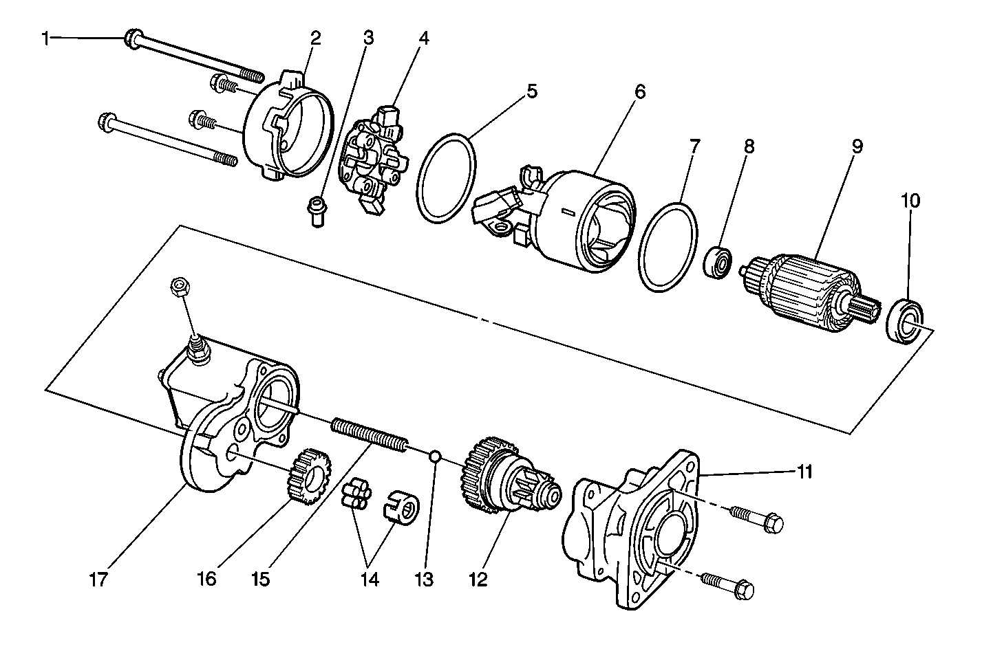
|
| Figure 2: |
Solenoid Assembly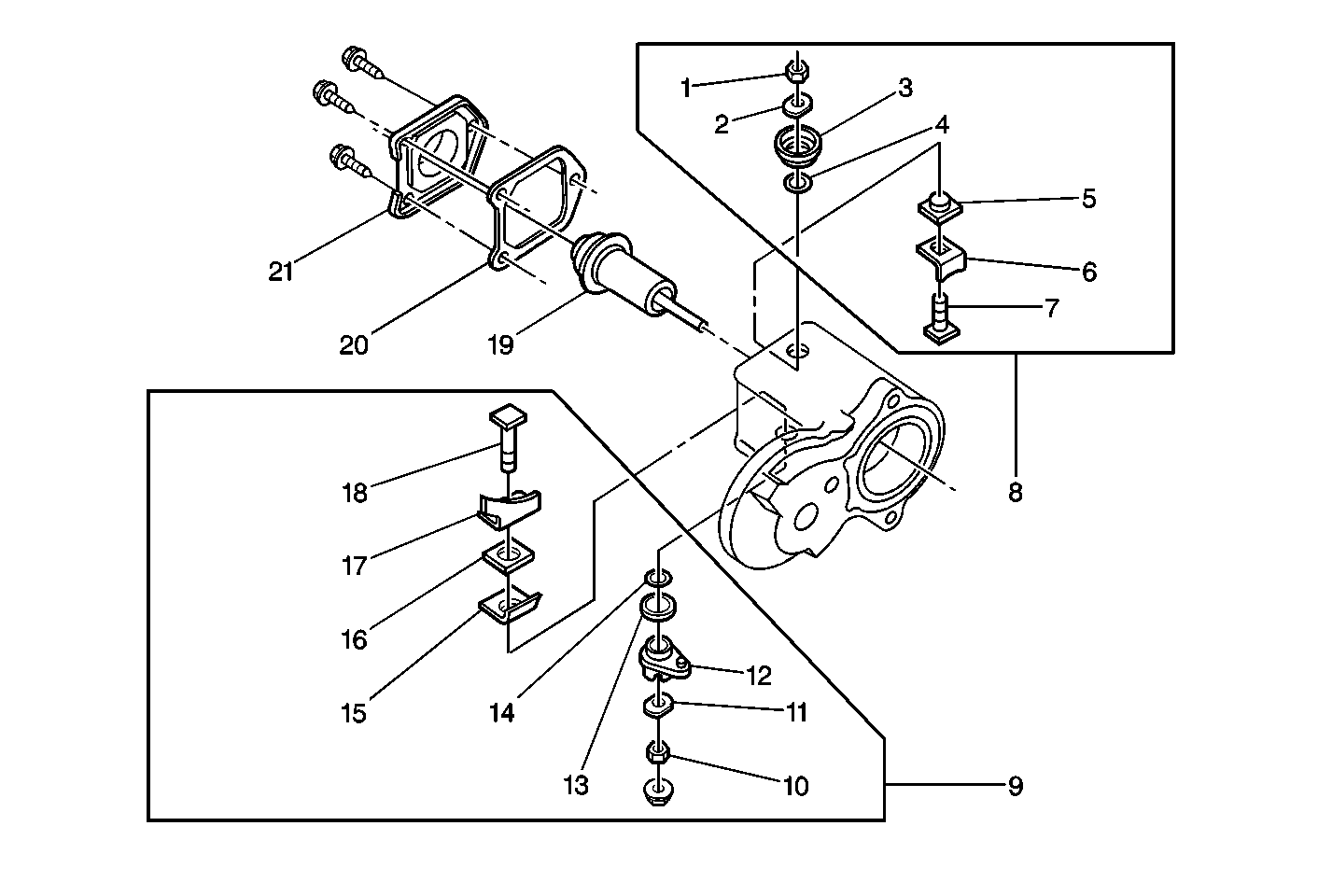
|
