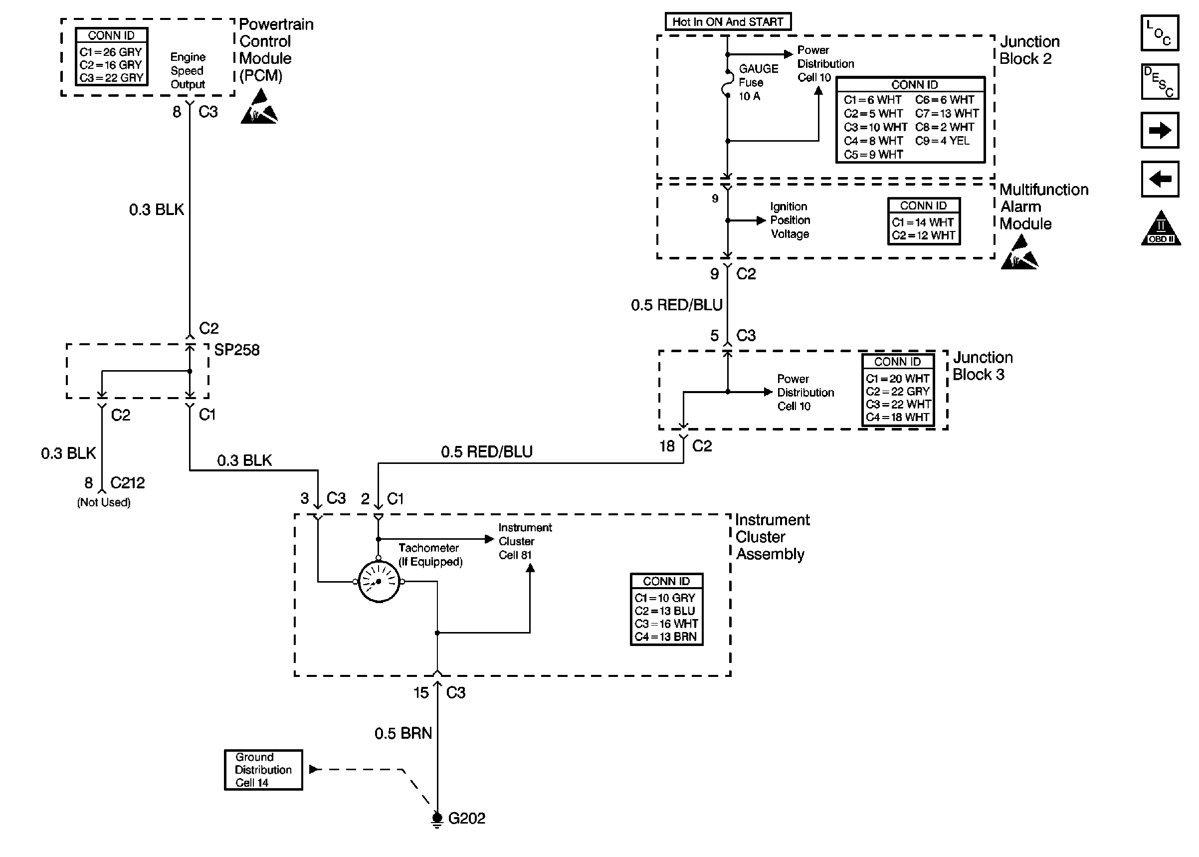
Refer to
Cell 20: Tachometer

schematics.
Circuit Description
The PCM generates an engine output speed signal based upon the crank
signal input. The engine speed output signal is sent to the Instrument Cluster
Assembly (ICA) to be displayed by the tachometer. The engine speed output
signal is a frequency signal that is near 22 Hz at idle and near
140 Hz at 4000 RPM.
The PCM also supplies a low current voltage on the engine speed output
signal circuit. The voltage on the engine speed output signal circuit is near
12 volts with the ignition ON and the engine OFF and near 7 volts with
the engine operating.
Test Description
-
This
step checks for the correct frequency output of the PCM.
-
When checking
for shorts to ground, resistance of more than 10K ohms is usually acceptable
although most readings should be infinite (OL).
When checking for circuit continuity (opens) resistance should be 5
ohms or less.
When checking for shorts to voltage take measurements with the ignition
ON and OFF. With the key ON and the engine OFF normal circuit voltage is near
12 volts, with the engine operating the PCM decreases this voltage to
near 7 volts.
Disconnect the circuit from all components before performing any circuit
check.
Always check or zero the meter before performing resistance checks.
Step
| Action
| Value(s)
| Yes
| No
|
1
| Did you
perform the Powertrain On-Board Diagnostic (OBD) System Check?
| --
|
Go to Step 2
| Go to
Powertrain On Board Diagnostic (OBD) System Check
|
2
| Operate the
vehicle while monitoring Instrument Cluster Assembly (ICA) operation.
Do all other ICA displays function correctly?
| --
|
Go to Step 3
| Go to
Instrument Cluster System Check
in Body and Accessories
|
3
|
- Start and idle the engine.
- Obtain normal operating temperature.
- Disconnect the ICA connector containing the engine speed output
circuit.
- Using the DMM J 39200 measure the frequency on the engine
speed output circuit at the ICA connector terminal with the engine idling.
Is the frequency measured near the value specified?
| 22 Hz
|
Go to Step 4
|
Go to Step 5
|
4
| While monitoring the DMM, vary
the engine speed between the RPM value range specified.
Does the frequency increase with the engine speed?
| Idle-3000 RPM
|
Go to Step 6
|
Go to Step 8
|
5
|
- Turn the ignition switch OFF.
- Disconnect PCM connector C3.
- Using the DMM check the engine speed output circuit for any of
the following:
| • | A short to another circuit |
| • | Refer to the Test Description. |
- Repair as necessary. Refer to
Wiring Repairs
in Wiring Systems.
Was a repair to the engine speed output circuit necessary?
| --
|
Go to Step 10
|
Go to Step 8
|
6
|
- Check terminal contact at the ICA connector.
- Repair terminal contact if needed.
Was terminal contact repaired?
| --
|
Go to Step
10
|
Go to Step 7
|
7
| Replace the ICA. Refer to
Instrument Cluster Replacement
in Body and Accessories.
Is the replacement complete?
| --
|
Go to Step
10
| --
|
8
|
- Check terminal contact at the PCM connector.
- Repair terminal contact if needed.
Was terminal contact repaired?
| --
|
Go to Step
10
|
Go to Step 9
|
9
| Replace the PCM. Refer to
Powertrain Control Module Replacement
.
Is the replacement complete?
| --
|
Go to Step
10
| --
|
10
|
- After repairs road test the vehicle under the conditions in which
this symptom was present.
- Check for symptom.
Is symptom present?
| --
|
Go to Step
2
| System OK
|

