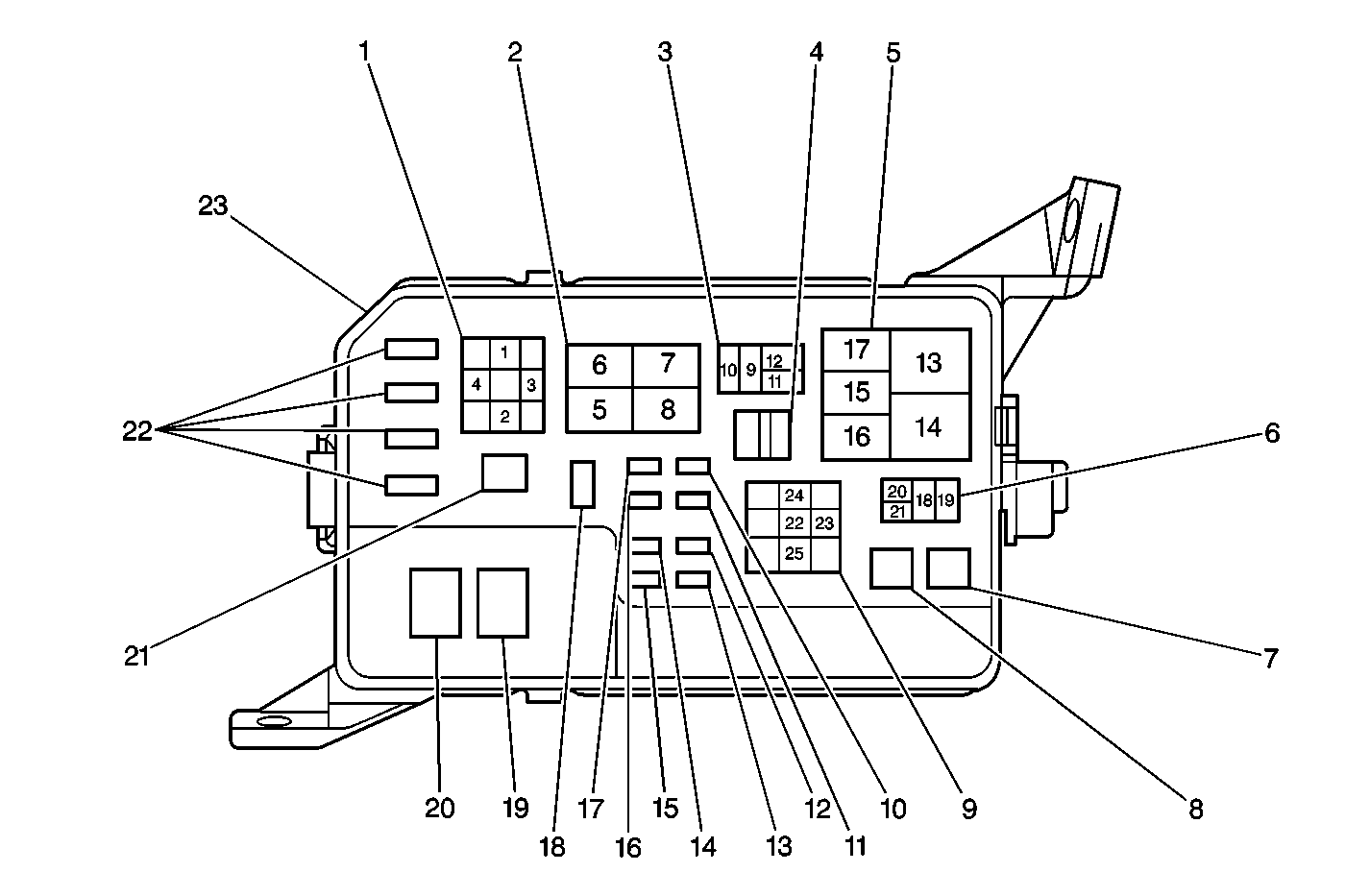
Step | Action | Yes | No | ||||||||||||||||||||||||||||||||||||
|---|---|---|---|---|---|---|---|---|---|---|---|---|---|---|---|---|---|---|---|---|---|---|---|---|---|---|---|---|---|---|---|---|---|---|---|---|---|---|---|
The auxiliary fan motor is mounted on the right side of the radiator/condenser assembly. The fans run at low speed (series configuration) when the A/C is operating and the engine coolant temperature (ECT) is below 83°C (181°F). The fans run at high speed (parallel configuration) when the ECT is above 93°C (199°F). A short to ground in the ground circuit of the A/C fan no. 1 and 2 relays will cause both fans to be inoperative once the ECT reaches 93°C (199°F). This table assumes that the main (left side) fan motor is functioning normally. | |||||||||||||||||||||||||||||||||||||||
The following are symptoms and possible causes.
| |||||||||||||||||||||||||||||||||||||||
1 | Did you perform the HVAC System Check? | Go to Step 2 | Go to HVAC System Check | ||||||||||||||||||||||||||||||||||||
2 |
Does the test lamp light? | Go to Step 3 | Go to Step 4 | ||||||||||||||||||||||||||||||||||||
3 | Replace the auxiliary fan motor. Refer to Engine Cooling Fan Replacement in Engine Cooling. Is the repair complete? | Go to HVAC System Check | -- | ||||||||||||||||||||||||||||||||||||
4 | Test for battery voltage at the auxiliary fan motor connector terminal 2. Is battery voltage present? | Go to Step 8 | Go to Step 5 | ||||||||||||||||||||||||||||||||||||
5 | Inspect the CDS fuse in fuse and relay block 2 for an open. Is the fuse open ? | Go to Step 6 | Go to Step 7 | ||||||||||||||||||||||||||||||||||||
6 | Repair the short to ground in the BLU/RED wire between the CDS fuse and the auxiliary fan motor connector terminal 2. Refer to Wiring Repairs in Wiring Systems. Is the repair complete? | Go to HVAC System Check | -- | ||||||||||||||||||||||||||||||||||||
7 | Repair the open in the BLU wire between the CDS fuse and fuse and relay block 1 OR in the BLU/RED wire between the CDS fuse and the auxiliary fan motor connector terminal 2. Refer to Wiring Repairs in Wiring Systems. Is the repair complete? | Go to HVAC System Check | -- | ||||||||||||||||||||||||||||||||||||
8 |
Is an open present? | Go to Step 10 | Go to Step 9 | ||||||||||||||||||||||||||||||||||||
9 | Replace the fan no. 2 relay. Refer to Condenser Fan Relay Replacement . Is the repair complete? | Go to HVAC System Check | -- | ||||||||||||||||||||||||||||||||||||
10 | Repair the open. Refer to Wiring Repairs in Wiring Systems. Is the repair complete? | Go to HVAC System Check | -- | ||||||||||||||||||||||||||||||||||||

