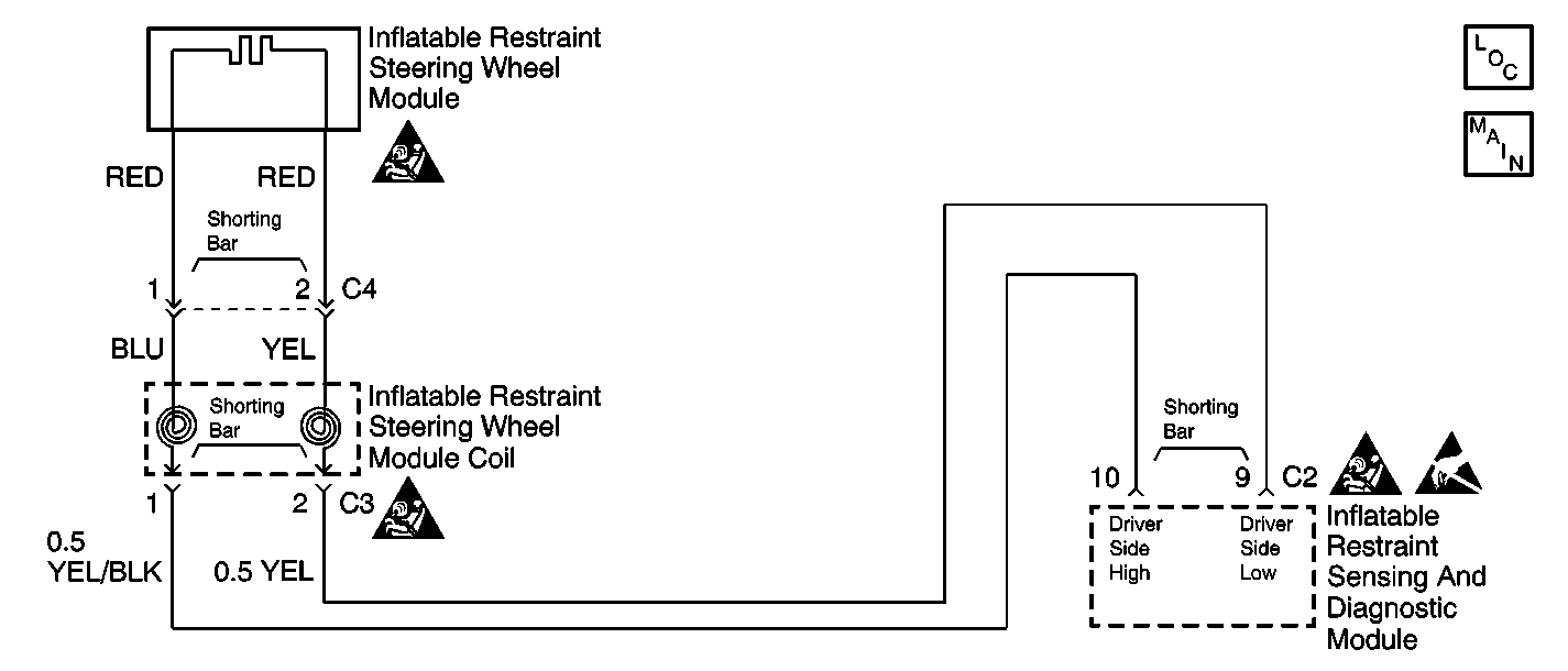
Circuit Description
When you first turn the ignition switch to the ON position, the inflatable restraint Sensing and Diagnostic Module (SDM) performs tests to diagnose critical malfunctions within itself. The SDM monitors the voltages at DRIVER SIDE LOW terminal 9 to detect shorts to ground in the inflator module circuits.
Conditions for Setting the DTC
The SDM detects a short to ground in the driver deployment loop.
Action Taken When the DTC Sets
| • | The SDM sets a Diagnostic Trouble Code. |
| • | The SDM turns ON the AIR BAG warning lamp. |
Conditions for Clearing the DTC
All DTCs are cleared with each ignition cycle.
Diagnostic Aids
A short to ground in the inflatable restraint steering wheel module circuit can cause an intermittent condition. Inspect the YEL/BLK and YEL wires leading to the steering wheel module carefully for cut or chafed wires.
Test Description
-
This test checks for a short to ground in the driver side high circuit.
-
This test determines if the malfunction is caused by the SDM.
-
This test determines if the malfunction is caused by the inflatable restraint steering wheel module.
-
This test checks for a short to ground in the inflatable restraint steering wheel module coil.
Step | Action | Value(s) | Yes | No |
|---|---|---|---|---|
1 | Was the SIR Diagnostic System Check performed? | -- | ||
Is the resistance measured equal to specified value? | OL (Infinite) | |||
Is DTC 11 present? | -- | |||
Is DTC 11 present? | -- | |||
Is the resistance measured equal to the specified values? | OL (Infinite) | |||
6 | Replace the inflatable restraint Sensing and Diagnostic Module (SDM). Refer to Inflatable Restraint Sensing and Diagnostic Module Replacement . Are all the repairs complete? | -- | -- | |
7 | Replace the inflatable restraint steering wheel module coil. Refer to Inflatable Restraint Steering Wheel Module Coil Replacement . Are all the repairs complete? | -- | -- | |
8 | Replace the inflatable restraint steering wheel module. Refer to Inflatable Restraint Steering Wheel Module Replacement . Are all the repairs complete? | -- | -- | |
9 | Repair the IP wiring harness between the steering wheel coil and the SDM. Refer to Wiring Repair . Are all the repairs complete? | -- | -- | |
10 | An intermittent exists in the driver deployment loop. Refer to diagnostic aids. Are all the repairs complete? | -- | -- | |
11 | Reconnect all SIR components. Make sure all components are properly mounted. Have all the SIR components been reconnected and properly mounted? | -- | -- |
