Tools Required
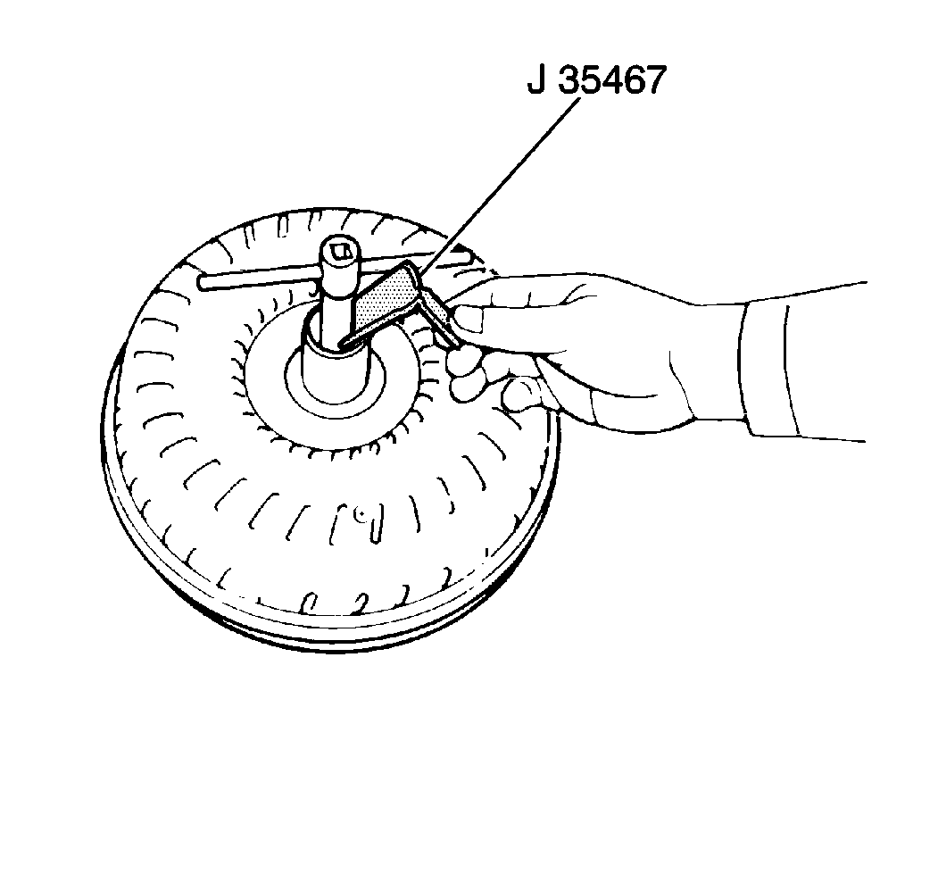
J 35467 One-Way
Clutch Tester

- Inspect the transmission
for contamination.
- Thoroughly flush the torque converter and transmission cooler
if any contamination of the transmission is evident.
- Insert a turning tool into the inner race of the one-way clutch.
- Install the stopper of the one-way clutch tester so that the stopper
fits into the notch of the converter hub and the other piece of the one-way
clutch.
- Use the following procedure to test the one-way clutch:
| 5.1. | Position the torque converter upward. |
| 5.2. | Rotate the one-way clutch counter clockwise using less than 2.5 N·m
(22 lb in) of torque. |
The one-way clutch should lock to pass the test.
| 5.3. | Rotate the one-way clutch clockwise using less than 2.5 N·m
(22 lb in) of torque. |
The one-way clutch should rotate freely and smoothly to pass the test.
- Perform the following steps if the one-way clutch fails the test:
| 6.1. | Clean the converter. |
| 6.2. | Retest the one-way clutch. |
| 6.3. | Replace the torque converter if the one-way clutch still fails
the test. |

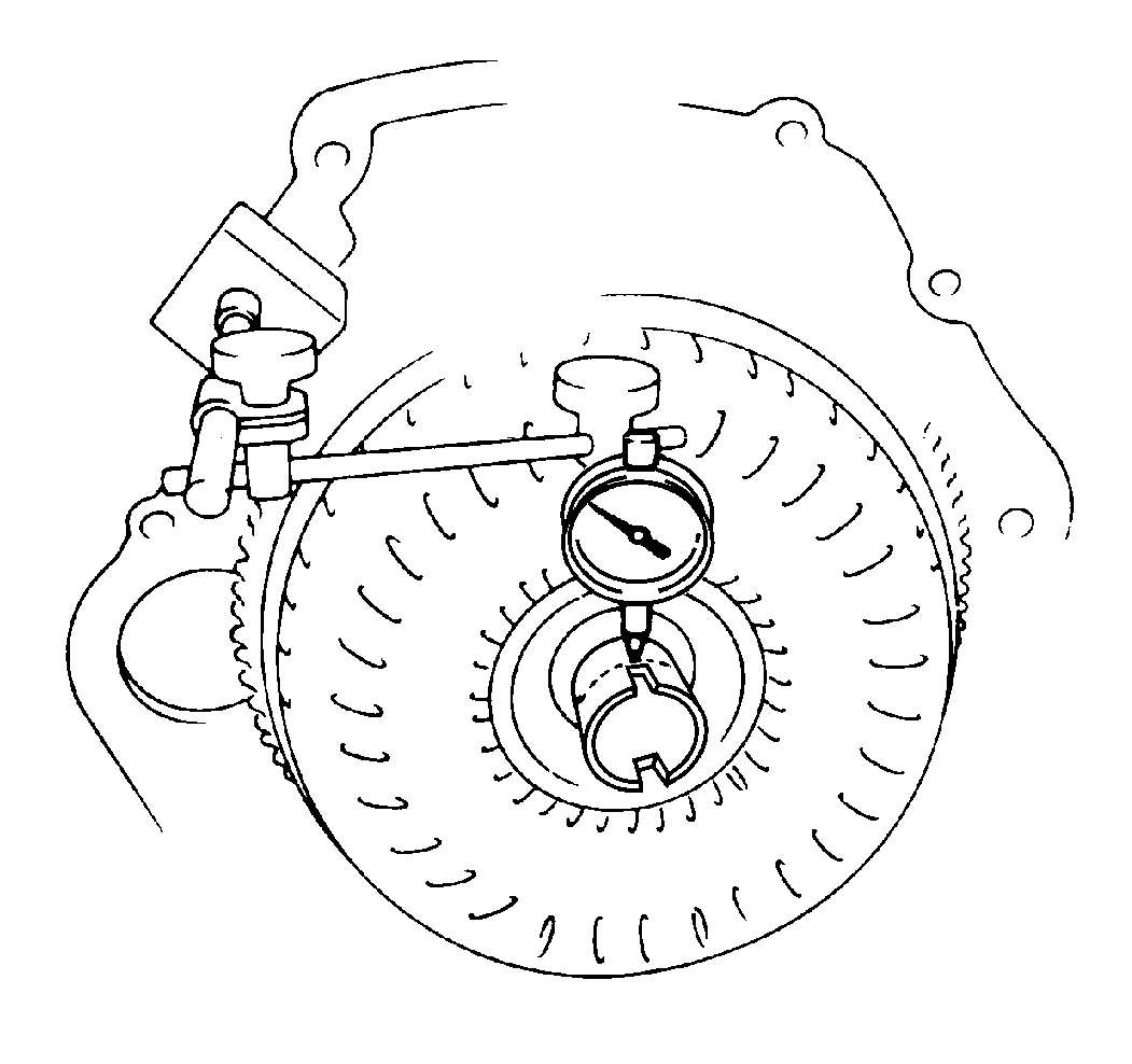
- Use the following procedure
to measure the torque converter sleeve runout:
| 7.1. | Mount the torque converter to the drive plate. |
| 7.2. | Set up a dial indicator. |
| 7.3. | Torque the dial indicator to 27 N·m (20 lb ft). |
- If the runout exceeds 0.30 mm (0.118 in), correct
the excessive runout by reorienting the installation of the torque converter.
- Replace the torque converter if the excessive runout cannot be
corrected.

Important: Scribe the position of the torque converter to ensure correct installation.
- Remove the torque converter from the drive plate.
Notice: Use the correct fastener in the correct location. Replacement fasteners
must be the correct part number for that application. Fasteners requiring
replacement or fasteners requiring the use of thread locking compound or sealant
are identified in the service procedure. Do not use paints, lubricants, or
corrosion inhibitors on fasteners or fastener joint surfaces unless specified.
These coatings affect fastener torque and joint clamping force and may damage
the fastener. Use the correct tightening sequence and specifications when
installing fasteners in order to avoid damage to parts and systems.
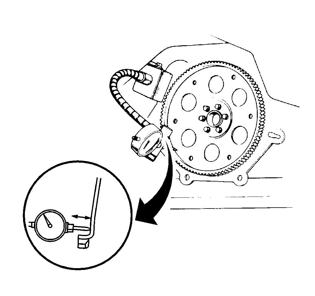
- Use the following procedure to measure the drive plate runout
and to inspect the ring gear:
| 11.1. | Set up a dial indicator. |
| 11.2. | Measure the drive plate runout. |
| 11.3. | Replace the drive plate if either of the following conditions
exists: |
| • | The drive plate runout exceeds 0.20 mm (0.0079 in). |
| • | The ring gear is damaged |
| 11.4. | Use the following procedure when installing a new drive plate: |
| • | Note the orientation of the drive plate spacers. |
Tighten
Tighten the drive plate bolts to 64 N·m (47 lb ft).


