Tools Required
| • | J 33411 Countergear Installer |
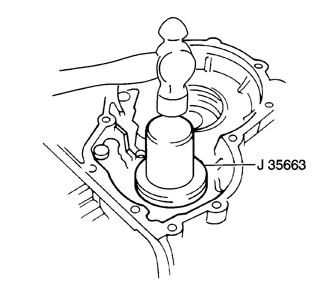
| • | J 35663 Counter Bearing Cup Installer |
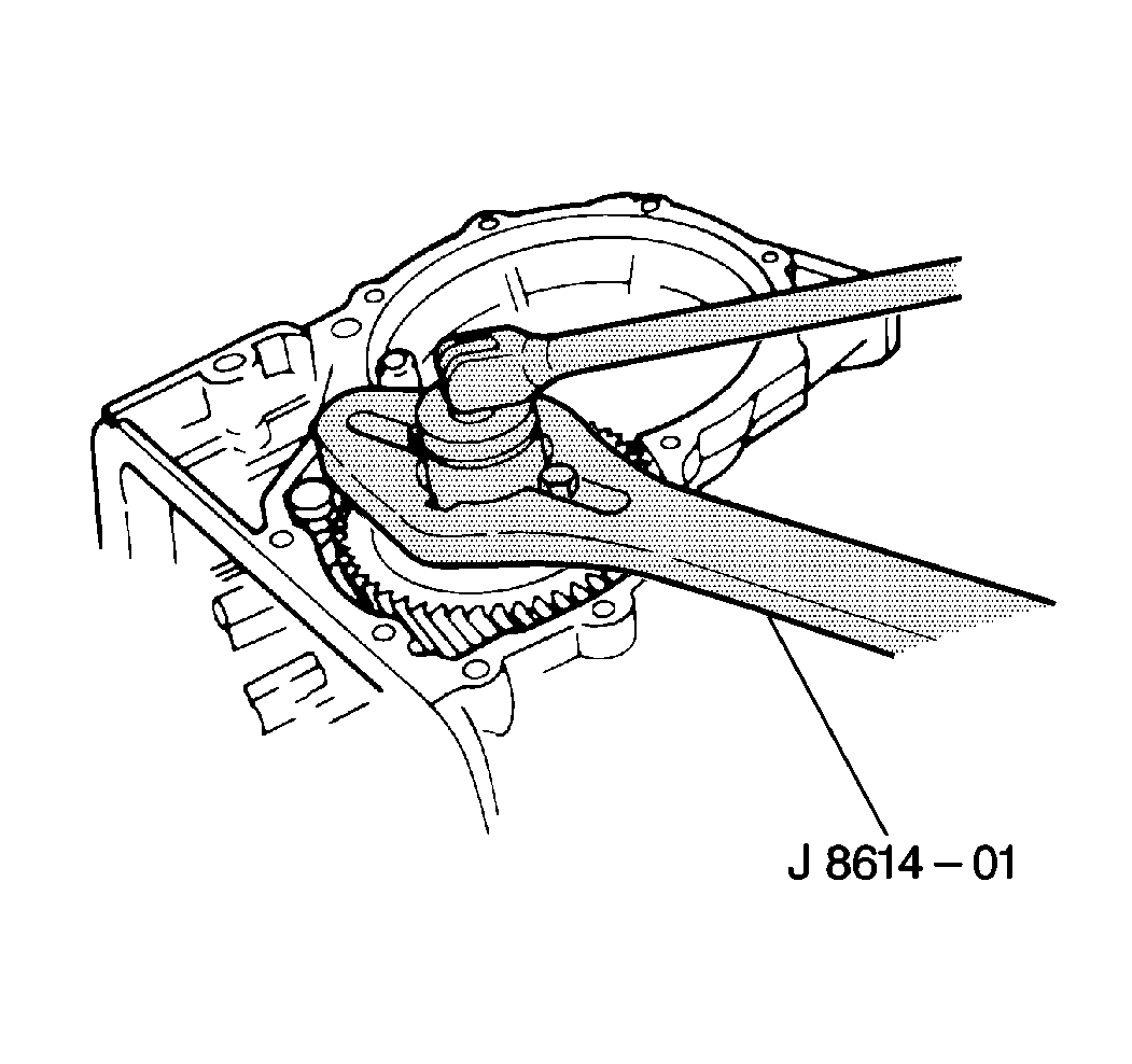
| • | J 8614-01 Countergear Holder |
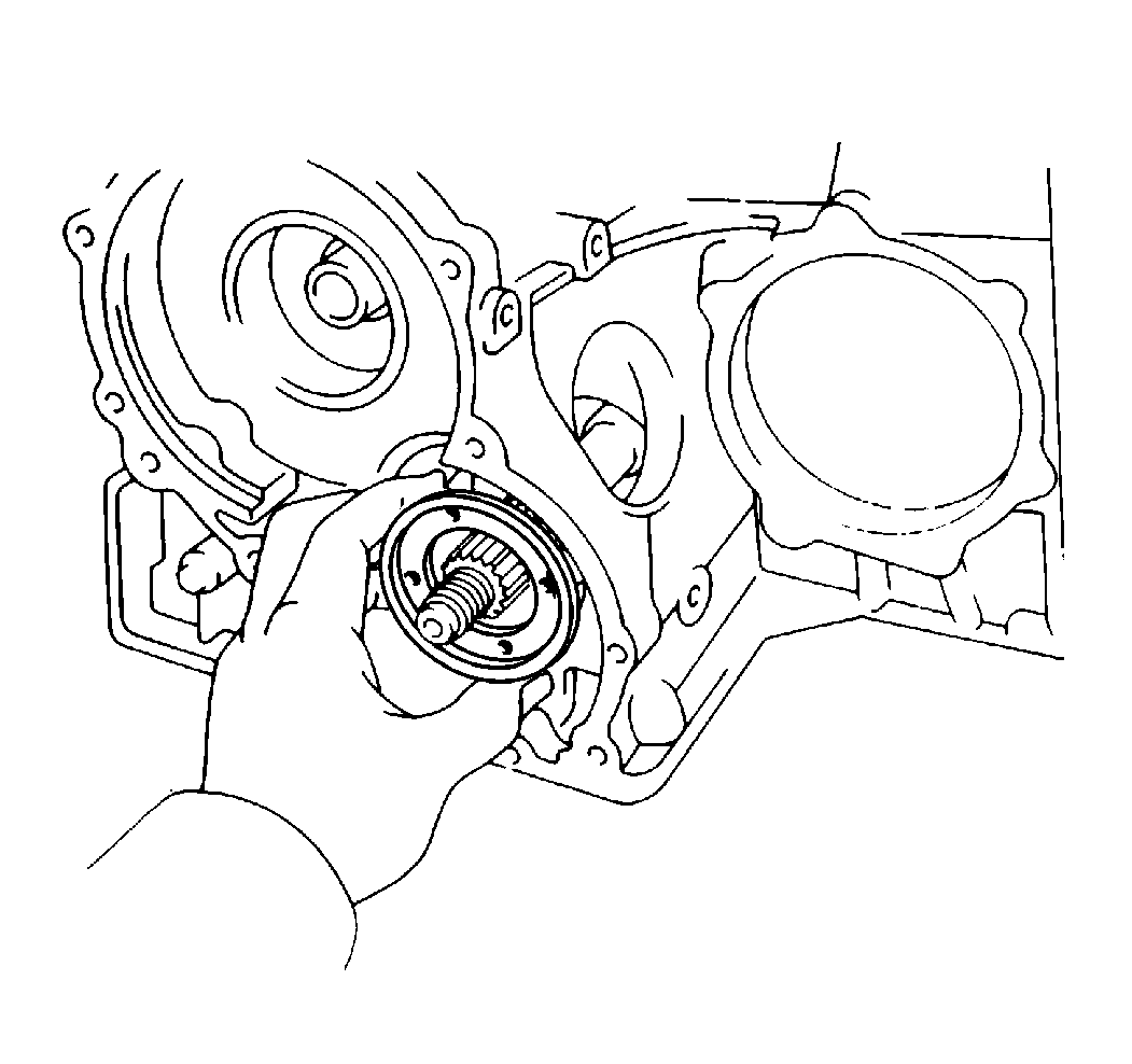
- Lightly tap the bearing cage into the case until you can see the groove with the bore.
- Push in the bearing cage until the surface of the bearing cage passes through the groove with the bore.
- Install a snap ring into the groove in the case.
- Lightly tap the drive pinion in order to fit the snap ring into the groove.
- Install the drive pinion end plug.
- Install the oil slinger.
- Use the J 35663 in order to drive the outer race into the case.
- Install a new spacer.
- Install the counter driven gear onto the shaft.
- Use the J 33411 in order to push the gear onto the shaft until the nut can be installed on the threads of the shaft.
- Use the J 8614-01 in order to install the counter driven gear nut.
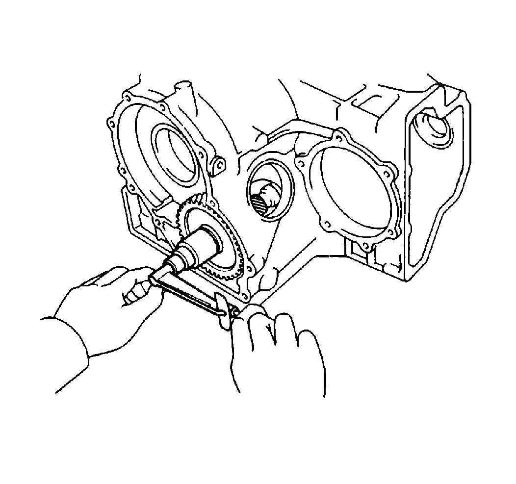
- Turn the counter driven gear counterclockwise and clockwise several times for smooth operation.
- Use a torque wrench in order to measure the preload of the drive pinion.
- Verify that the preload falls within the following measurement ranges:
- Replace the bearing spacer if the preload exceeds the specified range.
- If the preload falls below the specified range, continue tightening the counter driven gear nut.
- Use the following procedure if the preload exceeds the maximum torque specification while tightening the counter driven gear nut:
Notice: Use the correct fastener in the correct location. Replacement fasteners must be the correct part number for that application. Fasteners requiring replacement or fasteners requiring the use of thread locking compound or sealant are identified in the service procedure. Do not use paints, lubricants, or corrosion inhibitors on fasteners or fastener joint surfaces unless specified. These coatings affect fastener torque and joint clamping force and may damage the fastener. Use the correct tightening sequence and specifications when installing fasteners in order to avoid damage to parts and systems.
Tighten
Tighten the bolt to 13.6 N·m (10 lb ft).

The oil slinger lip should face upward.

Install the small end of the spacer first.
Important: Do not cause a shock to the transaxle case.

Tighten
Tighten the counter driven gear nut to 172 N·m (127 lb ft).

Important: Do NOT attempt to set the preload without first removing the differential carrier from the case.
Important: Do not back off the nut in order to reduce the preload.
The maximum possible torque is 289 N·m (231 lb ft).Measurement
| • | For a new bearing, the torque should measure 1.0-1.6 N·m (8.7-13.9 lb in). |
| • | For a reused bearing, the torque should measure 0.5-0.8 N·m (4.3-6.9 lb in). |
Tighten
Tighten the nut in increments of 13 N·m (115 lb in).
Continue tightening until the preload measures within the specified range.
| 17.1. | Replace the bearing spacer. |
| 17.2. | Repeat the preload procedure. |
