- Move the stabilizer shaft
from the left side of the vehicle toward the center of the vehicle in order
to install the stabilizer shaft to the vehicle.
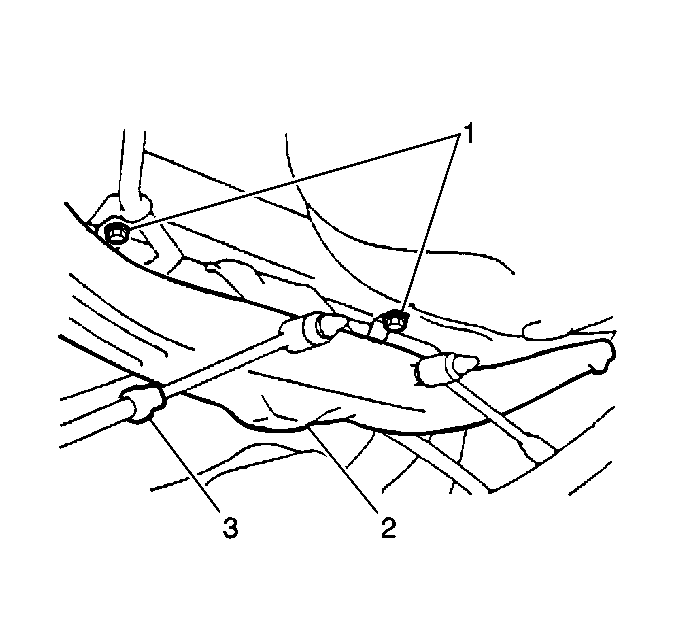
- Use a jack in order to raise the suspension crossmember (2).
Notice: Use the correct fastener in the correct location. Replacement fasteners
must be the correct part number for that application. Fasteners requiring
replacement or fasteners requiring the use of thread locking compound or sealant
are identified in the service procedure. Do not use paints, lubricants, or
corrosion inhibitors on fasteners or fastener joint surfaces unless specified.
These coatings affect fastener torque and joint clamping force and may damage
the fastener. Use the correct tightening sequence and specifications when
installing fasteners in order to avoid damage to parts and systems.
- Secure the suspension
crossmember with 6 bolts.
Tighten
| • | Tighten the outer rear suspension crossmember bolts to 74 N·m
(55 lb ft). |
| • | Tighten the inner rear suspension crossmember bolts to 19 N·m
(14 lb ft). |
- Remove the jack from the suspension crossmember.
- Reconnect the following hoses:
| • | The ORVR hoses to the EVAP canister |
| • | The filler neck vapor hoses to the fuel tank |
| • | The filler neck hose to the fuel tank |
- Install the right and left fuel tank bands. Secure the right and
left fuel tank bands using 1 bolt (1) for each band.
Tighten
Tighten the bolts to 39 N·m (29 lb ft).
- Remove the support from the fuel tank.

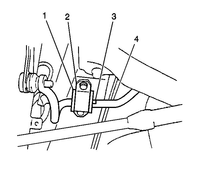
- Install the 2 stabilizer
shaft insulators (1) to the stabilizer shaft. Align the matchmarks.
Important: The weight of the vehicle must be on the tires and wheels before tightening
the nuts or the bolts.
- Install the right and left stabilizer shaft insulator clamps. Secure
the right stabilizer shaft insulator clamp using 2 bolts. Secure
the left stabilizer shaft insulator clamp using 2 bolts.

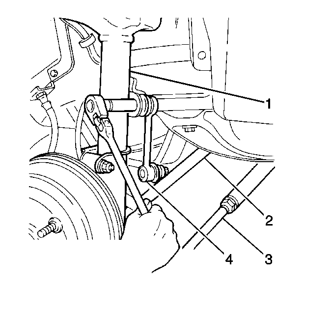
- Install the stabilizer
2 shaft links (4). Secure the 2 stabilizer shaft links
to the stabilizer shaft and the rear strut assemblies using 4 nuts.
- Install the strut assembly to the rear suspension knuckle using
2 nuts and 2 bolts.
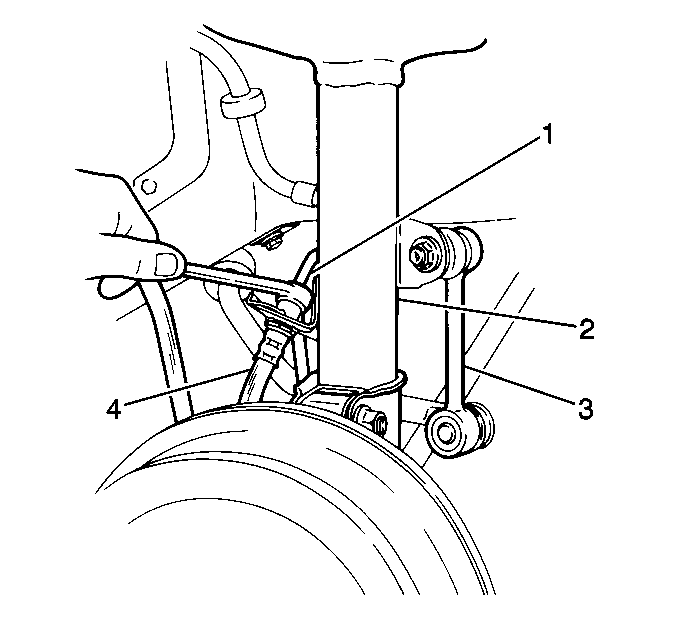
- Install the brake line clip.

- Install the brake hose
(4) to the strut assembly (2).
Tighten
Tighten the brake pipe fitting to 15 N·m (11 lb ft).
- Install the tire and wheel. Refer to
Tire and Wheel Removal and Installation
in Tires and Wheels.
- Lower the vehicle.
- Move the vehicle to a drive-on lift or an alignment rack.
- Bounce the vehicle up and down several times in order to stabilize
the suspension.

- Tighten the 4 bolts
on the 2 stabilizer shaft insulator clamps (2).
Tighten
Tighten the 4 bolts to 19 N·m (14 lb ft).
- Tighten the upper stabilizer shaft link nuts to the rear strut
assemblies.
Tighten
Tighten the nuts to 44 N·m (33 lb ft).
- Tighten the lower stabilizer shaft link nuts to the stabilizer
shaft.
Tighten
Tighten the nuts to 44 N·m (33 lb ft).
- Tighten the 2 nuts and the 2 bolts connecting the
rear strut assembly to the rear suspension knuckle.
Tighten
Tighten the 2 nuts and the 2 bolts to 142 N·m
(105 lb ft).
- Bleed the brake system. Refer to
Hydraulic Brake System Bleeding
in Hydraulic Brakes.
- Measure the rear wheel alignment. Adjust as necessary. Refer to
Wheel Alignment Measurement
in Wheel Alignment.


