Removal Procedure
- Remove the caliper from the vehicle. Refer to
Brake Caliper Replacement
.
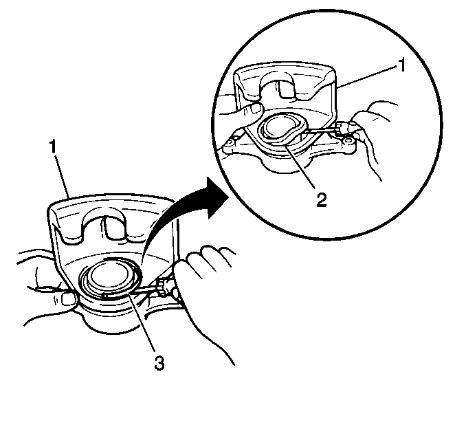
- Remove the caliper set
ring (3) and the piston boot (2).
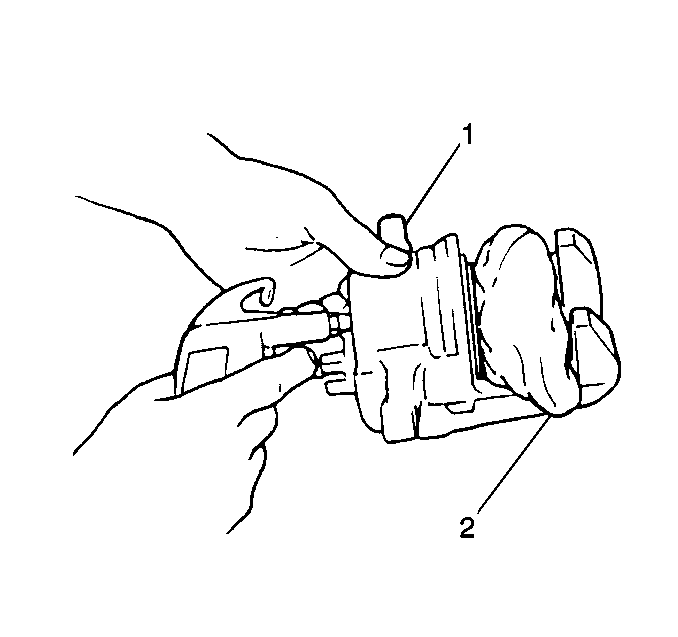
Caution: Do not place your fingers in front of the piston in order
to catch or protect the piston while applying compressed air. This could result
in serious injury.
- Insert a block of hard wood or a shop cloth (2) into the caliper
interior. This will catch the piston as the piston is forced out of the bore
with compressed air.
- Remove the piston from the caliper (1) by applying compressed
air to the caliper brake hose connector hole .
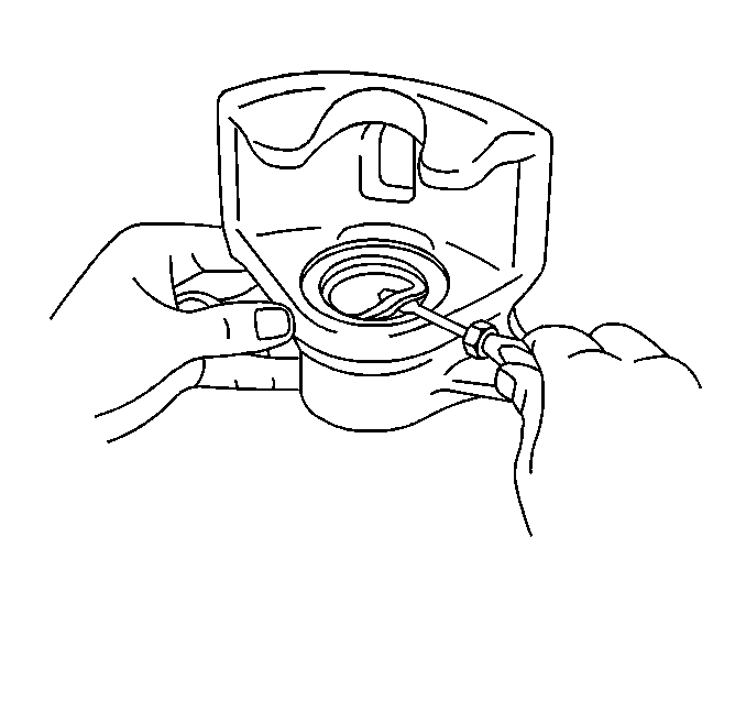
- Remove the piston seal
from the caliper housing by using a screwdriver.
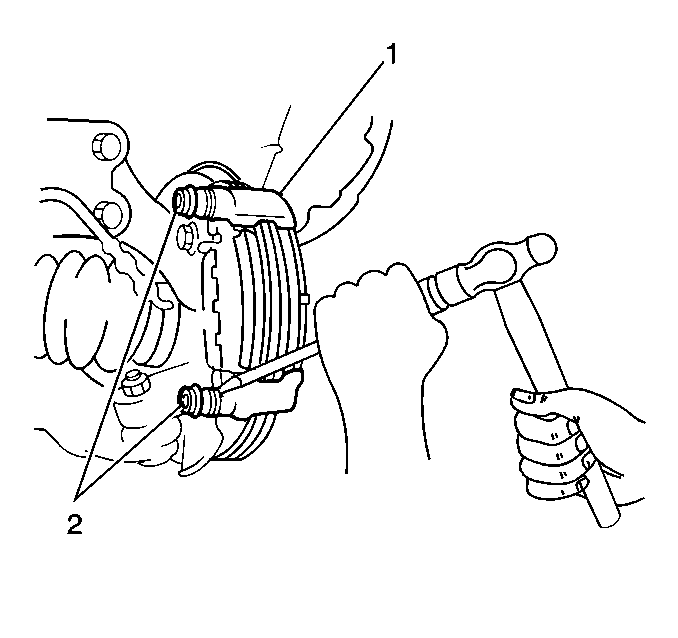
- Remove the sliding pins
from the caliper carrier (1).
- Remove the dust boots (2) from the caliper carrier using
a dull chisel and a hammer.
- Remove the bleeder valve from the caliper.
- Clean the following components in denatured alcohol:
| • | The caliper slide bushings |
- Dry the components using unlubricated, compressed air.
- Blow out all passages in the caliper housing and the bleeder valve.
- Inspect the following components for damage, wear or corrosion:
| • | The caliper slide bushing |
- Replace the components if damage, wear or corrosion is evident.
Installation Procedure
- Lubricate all rubber parts with clean brake fluid.
Notice: Use the correct fastener in the correct location. Replacement fasteners
must be the correct part number for that application. Fasteners requiring
replacement or fasteners requiring the use of thread locking compound or sealant
are identified in the service procedure. Do not use paints, lubricants, or
corrosion inhibitors on fasteners or fastener joint surfaces unless specified.
These coatings affect fastener torque and joint clamping force and may damage
the fastener. Use the correct tightening sequence and specifications when
installing fasteners in order to avoid damage to parts and systems.
- Install the bleeder
valve to the caliper.
Tighten
Tighten the bleeder valve to 8.3 N·m (74 lb in).
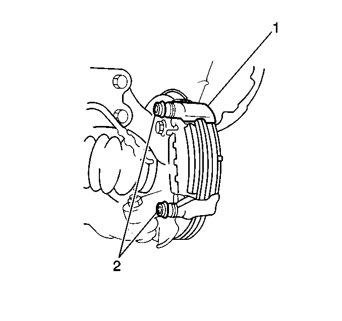
- Lubricate the 2 new dust boots (2) with Lubriplate®
Lubricant, GM P/N 12346293, or an equivalent lubricant meeting
the requirements of NLGI #2 Category LB or GC-LB.
- Install the 2 new dust boots (2) onto the caliper
carrier (1). Use a wrench and a hammer in order to tap the dust boots
onto the caliper carrier. Verify that the metal plate portion of the dust
boot fits snugly in the torque plate.
- Lubricate the 2 sliding pins with Lubriplate® Lubricant,
GM P/N 12346293, or an equivalent lubricant meeting the requirements
of NLGI #2 Category LB or GC-LB.
- Insert the sliding pin with the sliding bushing into the lower
portion of the torque plate.
- Insert the sliding pin without the sliding bushing into the upper
portion of the torque plate.
- Lubricate the following components with Lubriplate® Lubricant,
GM P/N 12346293, or an equivalent lubricant meeting the requirements
of NLGI #2 Category LB or GC-LB:
- Install the piston seal and piston into the caliper housing.
- Install the piston boot and caliper set ring into the caliper
housing.
Important: Ensure that the dust boots are secured firmly into each caliper groove.
- Install the caliper to the vehicle. Refer to
Brake Caliper Replacement
.


