Tools Required
J 39567 Booster
Push Rod Gauge
Removal Procedure
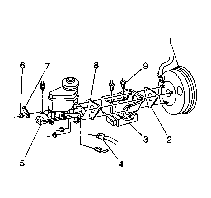
- Remove the master cylinder (5).
Refer to
Master Cylinder Replacement
.
- If the vehicle has ABS, remove the brake pressure modulator valve
assembly and the bracket (3). Refer to
Brake Pressure Modulator Valve Assembly Replacement
in Antilock Brake System.
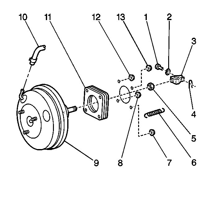
- Remove the hose clamp
and the hose (10) from the booster (9).
- Remove the brake pedal return spring (6).
- Remove the following components from the push rod clevis (3)
:
- Remove the following components from the bulkhead:
| • | The four mounting nuts (7,8,12,13) |
| • | The booster assembly (9) |
Installation Procedure
Notice: Use the correct fastener in the correct location. Replacement fasteners
must be the correct part number for that application. Fasteners requiring
replacement or fasteners requiring the use of thread locking compound or sealant
are identified in the service procedure. Do not use paints, lubricants, or
corrosion inhibitors on fasteners or fastener joint surfaces unless specified.
These coatings affect fastener torque and joint clamping force and may damage
the fastener. Use the correct tightening sequence and specifications when
installing fasteners in order to avoid damage to parts and systems.

- Install the following
components to the bulkhead:
| • | A new gasket (11) between the booster assembly (9)
and the bulkhead |
| • | The booster assembly (9) |
| • | Secure the booster assembly with the 4 nuts (7,8,12,13). |
Tighten
Tighten the nuts to 13 N·m (108 lb in).
- Install the clevis (3) to the operating rod.
- Install the following components to the clevis (3):
- Install the brake pedal return spring (6).

- If the vehicle has ABS,
install the following components to the booster assembly (5):
| 5.2. | The bracket for the brake pressure modulator valve assembly (3) |
| 5.3. | The 3 nuts. DO NOT torque the nuts. |
- Install a new gasket on the master cylinder.
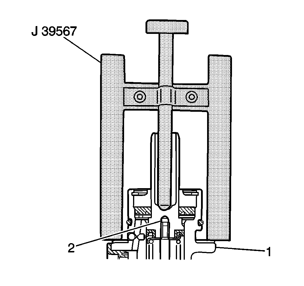
- Place the J 39567
on the gasket.
- Lower the J 39567
pin down until the pin touches the master cylinder piston (2).
- Remove the J 39567
from the master cylinder.
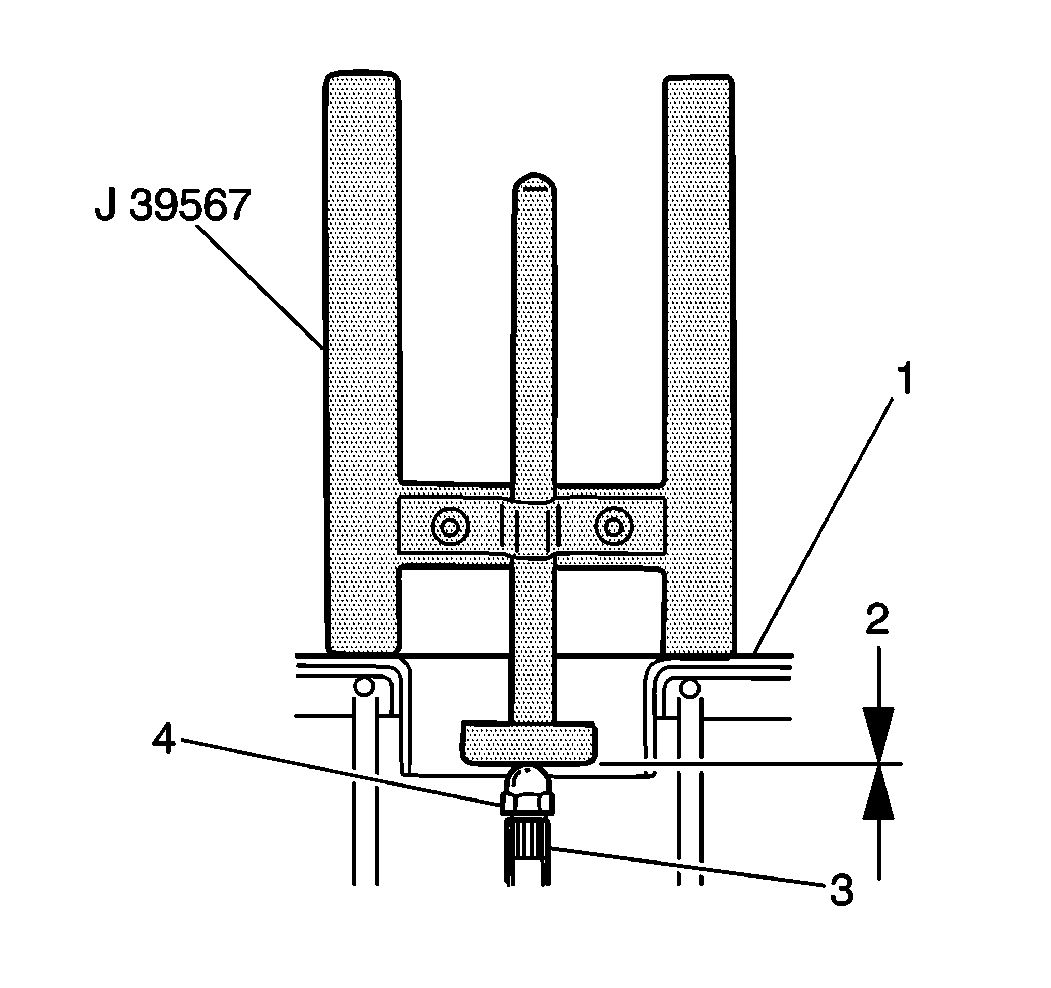
- Turn the J 39567
upside down.
- If the vehicle has ABS, place the J 39567
on the bracket for the brake pressure modulator valve assembly.
- If the vehicle does not have ABS, place the J 39567
on the booster assembly (1).
- Measure the clearance (2) between the booster piston rod (3)
and the J 39567
.
Specification
Ensure that the clearance is 0 mm (0 in).
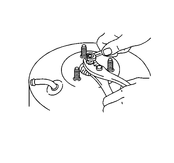
- If the booster piston
rod length does not match the specification, complete the following procedure:
| 14.1. | Ask an assistant to push the booster piston rod out by pressing
the brake pedal. |
| 14.2. | Turn the booster piston rod until the booster piston rod slightly
touches the pin head. |

- If the vehicle is equipped
with ABS, install the brake pressure modulator valve assembly (3).
Refer to
Brake Pressure Modulator Valve Assembly Replacement
in Antilock Brake System.
- Install the master cylinder (5). Refer to
Master Cylinder Replacement
.
- Torque the 3 master cylinder nuts.
Tighten
Tighten the three nuts to 13 N·m (108 lb in).
- Install the hose to the booster assembly (1).
Secure the hose with the hose clamp.
- Bleed the brake system. Refer to
Hydraulic Brake System Bleeding
.
- Inspect for leaks.
- Adjust the brake pedal travel. Refer to
Brake Pedal Travel Measurement and Inspection
.

- Tighten the clevis lock
nut (5).
Tighten
Tighten the nut to 26 N·m (19 lb ft).


